4-5
Catalyst 6500 Series Switches Installation Guide
OL-5781-04
Chapter 4 Removal and Replacement Procedures
Removing and Installing the AC-Input Power Supplies
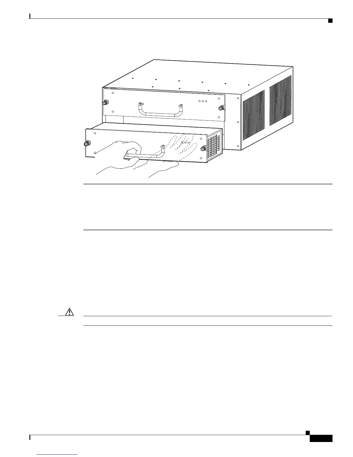
Figure 4-3 Handling an AC-Input Power Supply
Installing a 950 W or 1400 W AC-Input Power Supply
Follow these steps to install an AC-input power supply:
Step 1 Ensure that the system (earth) ground connection has been made. For ground connection instructions,
see the “Establishing the System Ground” section on page 3-22.
Step 2 If necessary, remove the blank power supply filler plate from the chassis power supply bay opening by
loosening the captive installation screws.
Step 3 Grasp the power supply handle with one hand. Place your other hand underneath the power supply, as
shown in Figure 4-3. Slide the power supply into the power supply bay. Make sure that the power supply
is fully seated in the bay.
Step 4 Securely tighten the power supply captive installation screws. (See Figure 4-2 for the Catalyst 6503 and
Catalyst 6503-E switches.)
Caution Power supply captive installation screws must be tight to ensure protective grounding continuity.
Step 5 At the front of the chassis, plug the power cord into the PEM.
63032
INP
UT
OK
FAN
O
K
OUTPUT
FA
IL
IN
PUT
O
K
FAN
OK
O
U
TP
UT
FAI L