4-8
Catalyst 6500 Series Switches Installation Guide
OL-5781-04
Chapter 4 Removal and Replacement Procedures
Removing and Installing the AC-Input Power Supplies
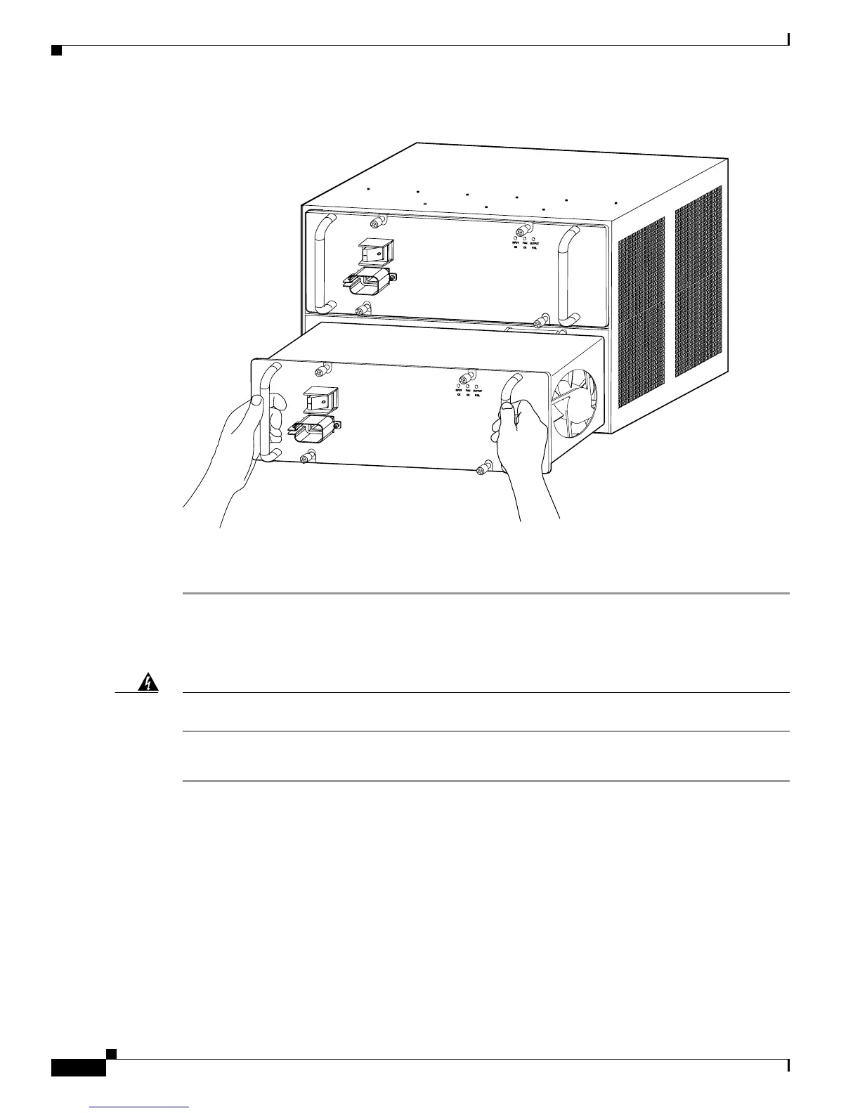
Figure 4-5 Handling a 2700 W AC-Input Power Supply
Step 6
If the power supply bay is to remain empty, install a blank power supply filler plate (Cisco
part number 800-16727-01) over the opening and secure it with the captive installation screws.
Installing a 2700 W AC-Input Power Supply
Warning
This product requires short-circuit (overcurrent) protection, to be provided as part of the building
installation. Install only in accordance with national and local wiring regulations.
Statement 1045
To install an AC-input power supply, follow these steps:
Step 1 Ensure that the system (earth) ground connection has been made. For ground connection instructions,
see the “Establishing the System Ground” section on page 3-22.
Step 2 If necessary, remove the blank power supply filler plate from the chassis power supply bay opening by
loosening the captive installation screws.
Step 3 Verify that the power switch on the power supply is in the Off (0) position.
Step 4 Grasp both power supply handles. (See Figure 4-5.) Slide the power supply into the power supply bay.
Make sure that the power supply is fully seated in the bay.
Step 5 Securely tighten the power supply captive installation screws.
130890
ALL FASTERNERS MUST BE FULLY ENGAGED
PRIOR TO OPERATING THE POWER SUPPLY
PWR-2700-AC
ALL FASTERNERS MUST BE FULLY ENGAGED
PRIOR TO OPERATING THE POWER SUPPLY
PWR-2700-AC