4-30
Catalyst 6500 Series Switches Installation Guide
OL-5781-04
Chapter 4 Removal and Replacement Procedures
Removing and Installing the DC-Input Power Supplies
Step 7 Connect the DC-input wires to the 2700 W power supply terminal block (Figure 4-22) in this order:
• Ground
• Negative (-)
• Positive (+)
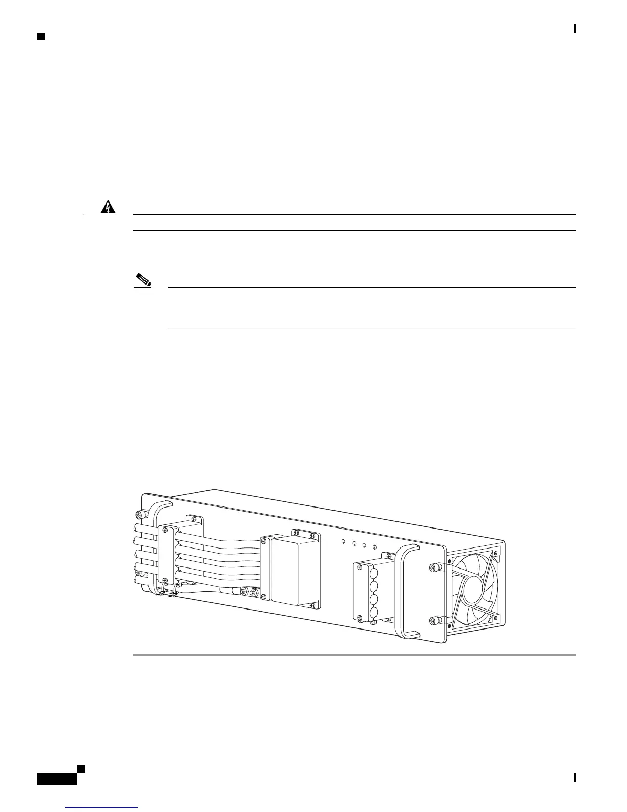
Depending on which side you are connecting the DC-input wires, be sure that the DC-input wires rest in
the appropriate cable holder. Figure 4-23 shows DC-input wires coming in from the left side.
Step 8 Secure the ground cable to the cable holder with the two cable-ties.
Warning
When installing the unit, always make the ground connection first and disconnect it last.
Statement 42
Step 9 Retrieve the cable holder covers from the plastic bag and attach to the front panel at the locations shown
in Figure 4-22.
Note If the cable holder illustrated a number 5 and number 8 in Figure 4-22 is loose on the DC input
cables, we recommend that you use a long cable tie wrap to secure the cable holders as shown
in the figure.
Step 10 Secure the terminal block cover using four screws and the terminal block barriers with two screws each.
Step 11 Turn on the DC inputs and verify power supply operation by checking that the power supply front panel
LEDs are in the following states:
• INPUT OK LED is green
• FAN OK LED is green
• OUTPUT FAIL LED is not lit
If the LEDs indicate a power problem, see the “Identifying Startup Problems” section on page E-3.
Figure 4-23 DC-Input Wires on Left Side
132220
IN
PU
T1
O
K
48V-60V
=40A
IN
PU
T2
O
K
48V
-60V
=40A
FA
N
O
K
O
U
TPU
T
FA
IL
ALL FASTENERS MUST BE FULLY ENGAGED
PRIOR TO OPERATING THE POW
ER SUPPLY
PWR-2700-DC/4