4-32
Catalyst 6500 Series Switches Installation Guide
OL-5781-04
Chapter 4 Removal and Replacement Procedures
Removing and Installing the DC-Input Power Supplies
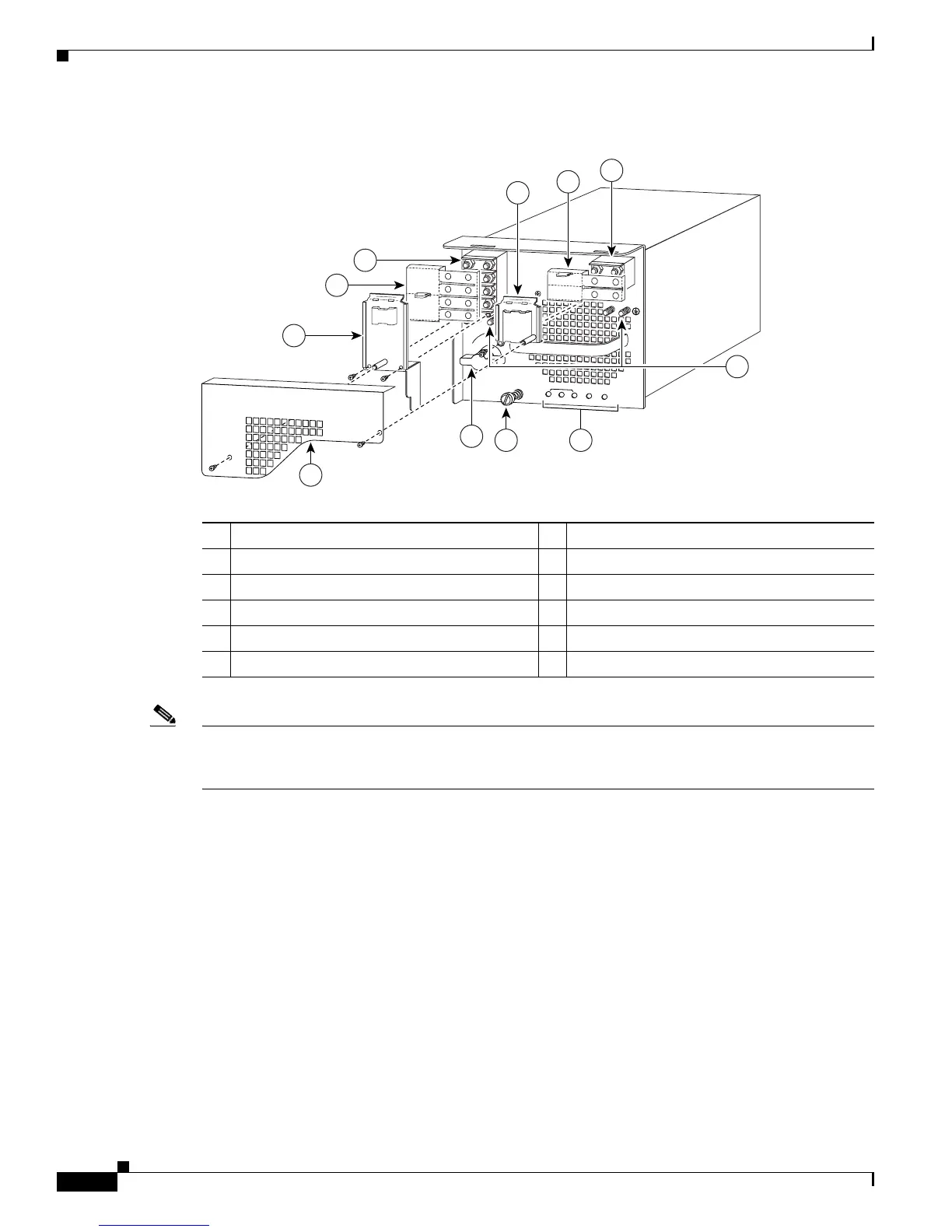
Figure 4-24 DC-Input Front Panel for 4000-W DC-Input Power Supply
Note Figure 4-24 shows the PWR-4000-DC power supply with an outer terminal block cover. An earlier
version of this power supply does not have an outer terminal block cover. To order a retrofit kit
containing this cover, use Cisco Systems part number CVR-4000DC-TERM=.
1 Inner terminal block cover 7 Power switch
2 Plastic insulator 8 Outer terminal block cover
3 DC power cable terminal block 2 (TB2) 9 Inner terminal block cover
4 Ground 10 Plastic insulator
5 Status LEDs 11 DC power cable terminal block 1 (TB1)
6 Captive installation screw
INP
U
T O
K
FA
N
O
K
O
U
TPU
T
FAI L
I
0
101397
1
3
2
5
11
6
3
1
10
+
VE-1
-
VE-1
+
VE
-2
-
VE-2
+
V
E-3
-
VE-3
8
7
9
4
2