4-35
Catalyst 6500 Series Switches Installation Guide
OL-5781-04
Chapter 4 Removal and Replacement Procedures
Removing and Installing the DC-Input Power Supplies
Installing a 4000 W DC-Input Power Supply
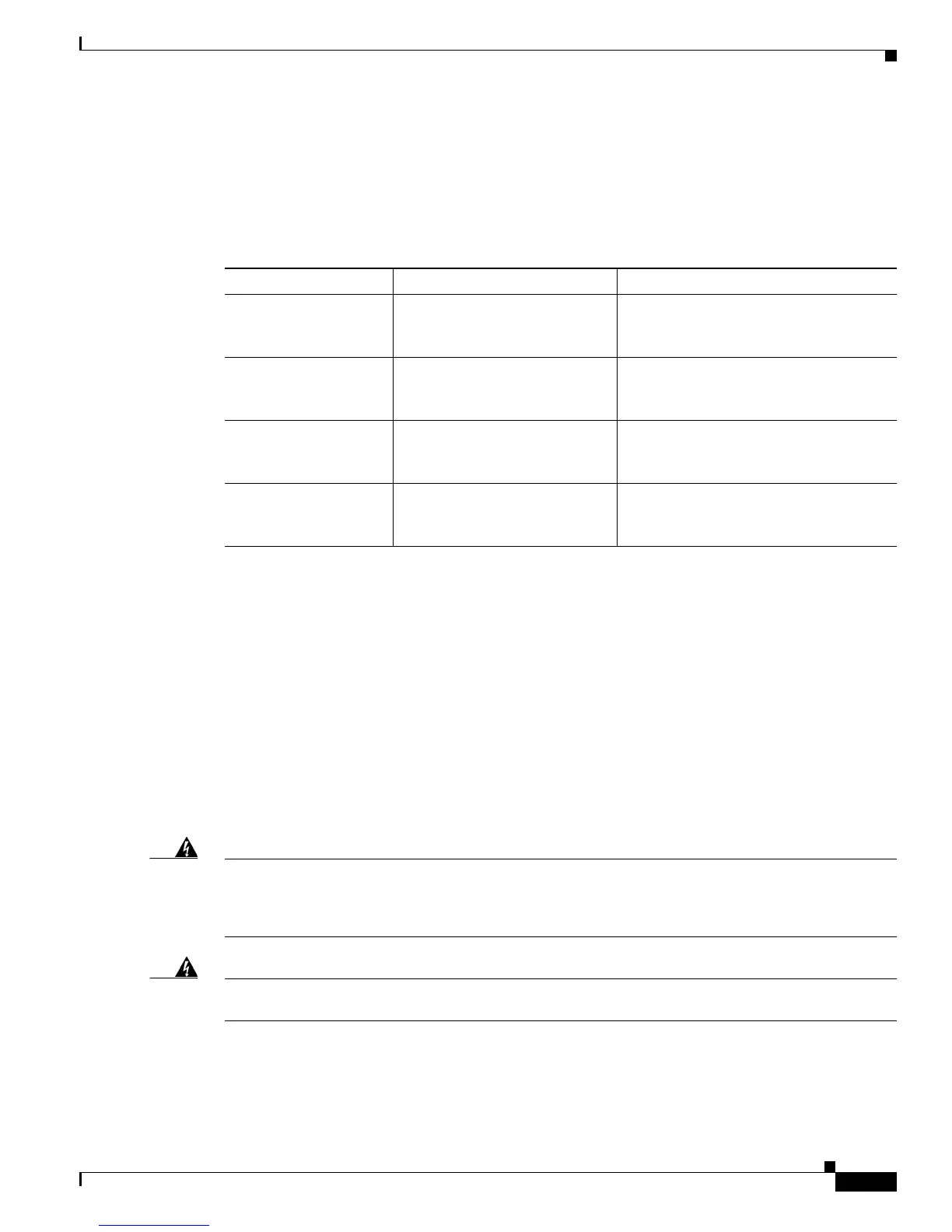
The 4000 W DC-input power supply can be wired for 2700 W or 4000 W operation. The type of
installation that you are performing determines the number of power cables and how they are routed.
Refer to Table 4-2 to select the appropriate installation procedure for your site.
Observe the following guidelines when installing a 4000 W DC-input power supply:
• For proper 4000 W DC-input redundant power configuration, all three pairs of input wires for one
4000 W DC-input power supply must come from the same battery system (A feed), and all three
pairs of input wires for the second 4000 W DC-input power supply must come from a different
battery system (B feed).
• The 4000 W DC-input power supply can operate at either 2700 W or 4000 W. To operate at 2700 W,
you can wire any two positive (+)/negative (-) terminal pairs in any sequence. To operate at 4000 W,
wire all three terminal pairs.
• For a single 4000 W DC-input power supply installation, install the power supply in the left-side
power bay (POWER 1).
• The 4000 W DC-input power supply will not operate with only one positive (+)/negative (-) terminal
pair installed.
Warning
Before performing any of the following procedures, ensure that power is removed from the DC
circuits. To ensure that all power is removed, locate the circuit breakers or fuses on the DC power
lines that service the DC circuits. Turn OFF the DC power line circuit breakers and remove the DC
power line fuses.
Statement 322
Warning
Power supply captive installation screws must be tight to ensure protective grounding continuity.
Statement 289
Figure 4-27 shows a 4000 W DC-input power supply.
Table 4-2 4000 W DC-Input Power Supply Installation Options
If you are wiring for... And you are installing... Use this procedure:
2700 W operation A single 4000 W power supply “Installing the 4000 W Power Supply
(Wiring for 2700 W Operation; Left
Power Bay)” section on page 4-37
2700 W operation A redundant (second) 4000 W
power supply
“Installing the 4000 W Power Supply
(Wiring for 2700 W Operation; Right
Power Bay)” section on page 4-40
4000 W operation A single 4000 W power supply “Installing the 4000 W Power Supply
(Wiring for 4000 W Operation; Left
Power Bay)” section on page 4-44
4000 W operation A redundant (second) 4000 W
power supply
“Installing the 4000 W Power Supply
(Wiring for 4000 W Operation; Right
Power Bay)” section on page 4-47