4-46
Catalyst 6500 Series Switches Installation Guide
OL-5781-04
Chapter 4 Removal and Replacement Procedures
Removing and Installing the DC-Input Power Supplies
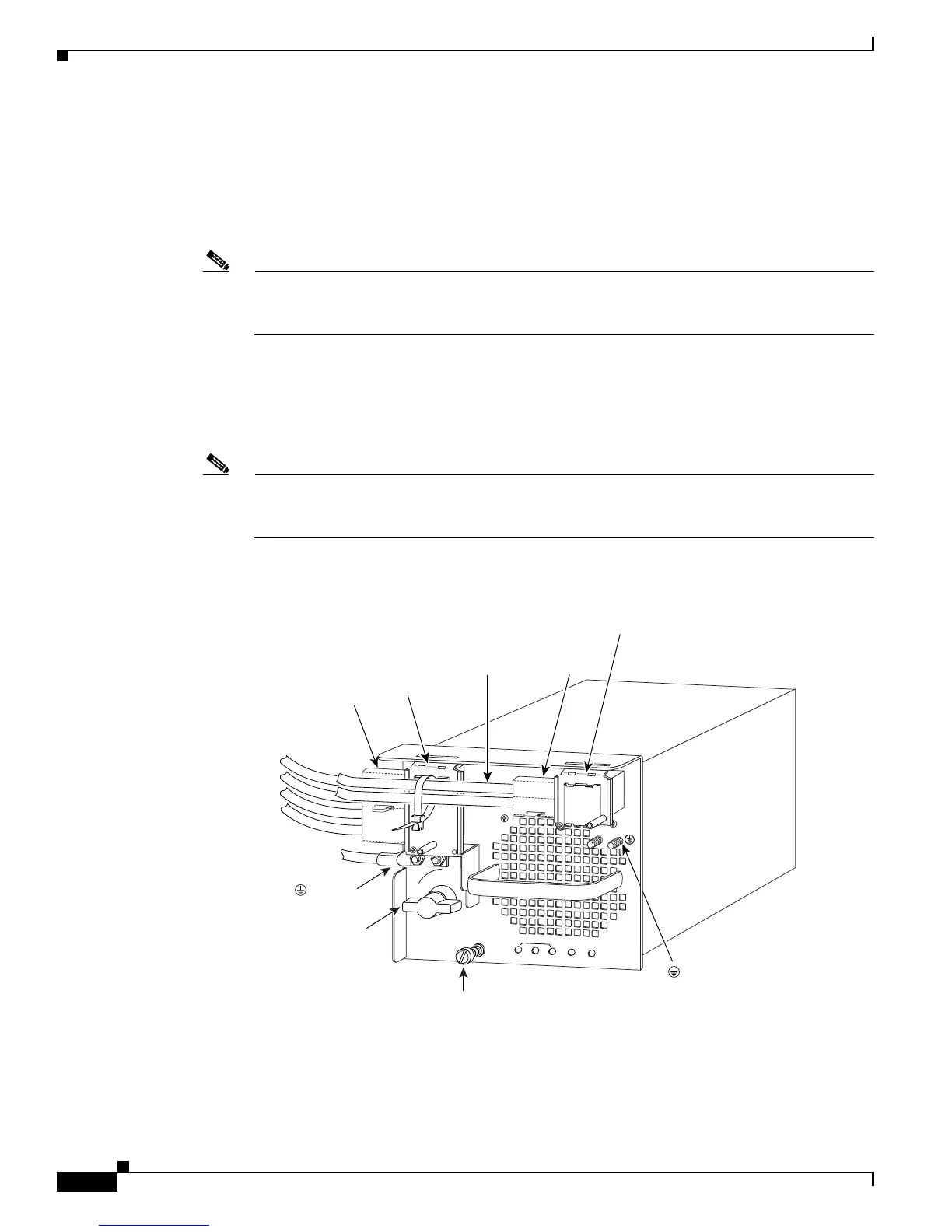
Step 10 From the left side of the power supply, connect the DC-input wires to the left power supply terminal
block (Figure 4-36) in this order:
1. Ground
2. Negative (-)
3. Positive (+)
Note When you tighten the terminal nuts, make sure that they are snug. Do not overtighten them.
Overtightening the terminal nuts can break the terminal block. (Maximum torque:
36 inch-pounds.)
Step 11 From the left side of the power supply, connect the DC-input wires to the right power supply terminal
block (Figure 4-36) in this order:
1. Negative (-)
2. Positive (+)
Note When you tighten the terminal nuts, make sure that they are snug. Do not overtighten them.
Overtightening the terminal nuts can break the terminal block. (Maximum torque:
36 inch-pounds.)
Figure 4-36 DC-Input Wire Connections for 4000 W Operation (Left-Side Power Bay)
114008
3
INPUT OK
FAN
OK
OUTPUT
FAIL
I
0
1
2
Captive
installation
screw
( ) Ground
(+) Positive
( - ) Negative
Power
switch
( ) Ground
(+) Positive
( - ) Negative
Power leads
attached to
terminal block
Terminal
block cover
Plastic
insulator
Power leads
attached to
terminal block
(+) Positive
( - ) Negative
Terminal
block cover
Plastic
insulator