A-36
Catalyst 6500 Series Switches Installation Guide
OL-5781-04
Appendix A Power Supply Specifications
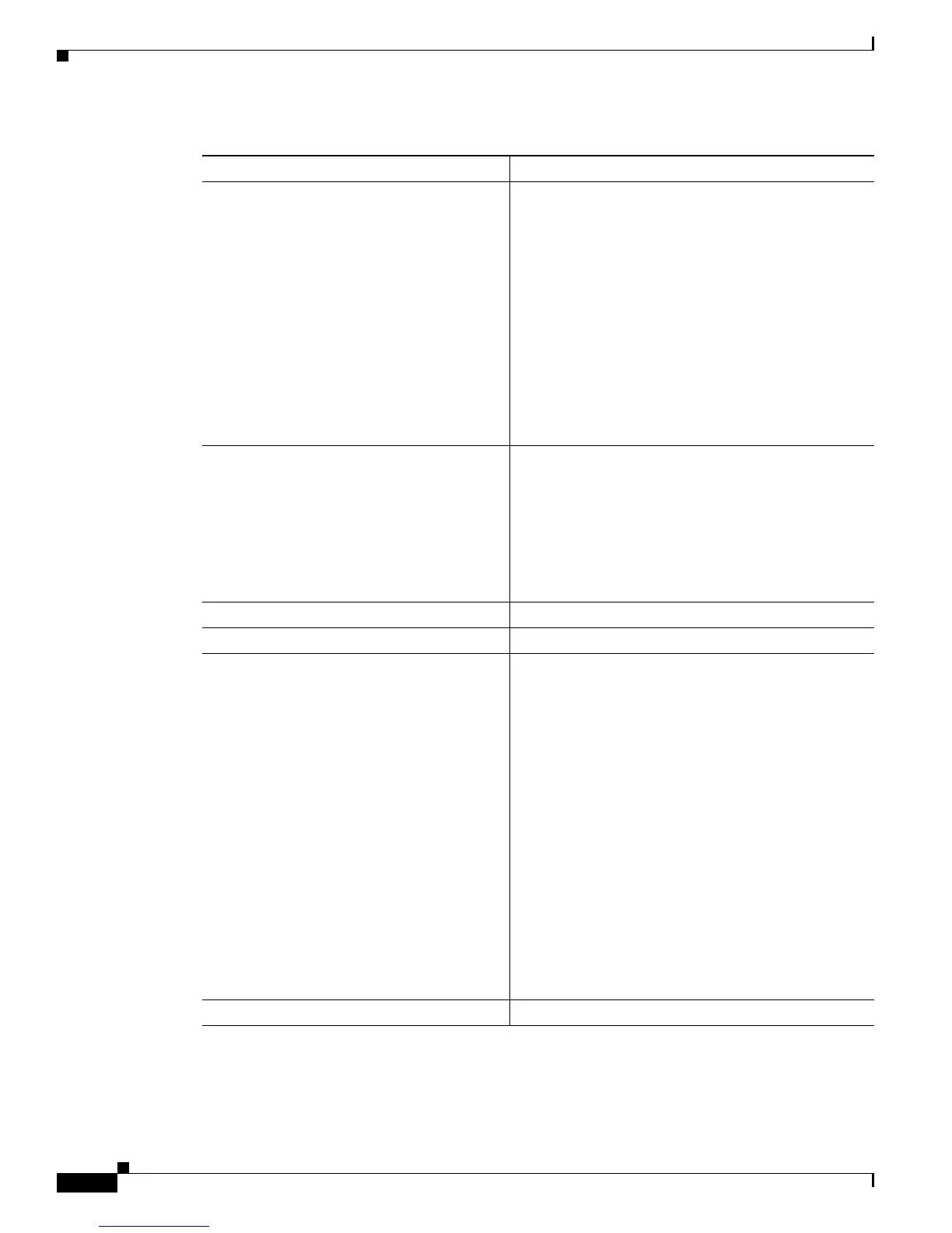
3000 W AC-Input Power Supply
Power supply output • 100/120 VAC operation
–
25.0 A @ +3.3 V
–
5A @ +5V
–
12 A @ +12 V
–
27.89 A @ +42 V
• 200/240 VAC operation
–
25.0 A @ +3.3 V
–
5A @ +5V
–
12 A @ +12 V
–
65.98 A @ +42 V
Front panel power connector A two-pin male Molex connector is located in the
lower right corner of the power supply front panel. The
connector provides 42 VDC at a maximum of 17 A.
This connector provides power to the
WS-6509-NEB-UPGRD kit fan assembly through a
power harness also provided in the kit. A hinged
protective flap secured by a captive screw covers the
connector when it is not in use.
Output holdup time 20 ms minimum
Heat Dissipation 12,046 BTU/hour (approx.)
Front panel LEDs
• INPUT OK • Green—Source AC voltage is OK. (Input voltage
is 85 VAC or greater.)
• Off—Source AC voltage falls below 70 VAC, is
not present, or the power supply is turned off.
• FAN OK • Green—Power supply fan is operating properly.
• Off—Power supply fan failure is detected.
• OUTPUT FAIL • Red—Problem with one or more of the DC-output
voltages of the power supply.
• Off—DC-output voltages within acceptable
margins.
• 42V OK • Green—42 VDC is present at the fan power
connector.
• Off—42 VDC is not present at the fan power
connector.
Weight 15.8 lb (7.2 kg)
Table A-15 3000 W Power Supply Specifications (continued)
Specification Description