2-7
Catalyst 6500 Series Switch Module Installation Guide
78-15725-02
Chapter 2 Preparing for Installation
Determining Cable Distances
10-Gigabit Ethernet
Table 2-8 lists the fiber-optic transmission specifications for the 10-Gigabit
Ethernet interfaces. Table 2-9 lists the optical power specifications for the
10-Gigabit Ethernet interfaces.
Caution To prevent severe damage to the WS-G6483 Optical Interface Module receiver,
you must install a 5-dB 1550 nm fixed-loss attenuator when fiber-optic cable
lengths are less then 12.4 miles (20 km). To prevent severe damage to the
WS-X6501-10GEX4 receiver, you must install a 5-dB 1550 nm fixed-loss
attenuator when fiber-optic cable lengths are less then 6.2 miles (10 km).
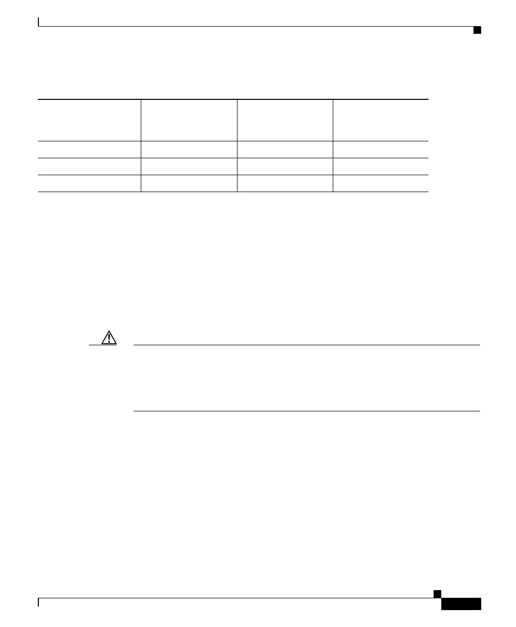
Table 2-7 GBIC Channel Insertion Loss
GBIC Device
Transmitter output
power
(min/max dBm)
Receiver maximum
input power (dBm)
Receiver minimum
sensitivity (dBm)
1000BASE-SX -9.5/-4 0 -17
1000BASE-LX/LH -9.5/-3 -3 -19
1000BASE-ZX 0/5 -3 -23
1
1. The 1000BASE-ZX GBIC provides a minimum optical power budget of 23dB. To determine the supported
link distance, you should measure your cable plant with an optical loss test set to verify that the optical loss
of the cable plant (including connectors and splices) is less than or equal to this value. The optical loss
measurement must be performed using a 1550 nm light source.
 Loading...


