Appendix B Cable and Connector Specifications
Supervisor Engine Console Port Signals and Pinouts
B-10
Catalyst 6500 Series Switch Module Installation Guide
78-15725-02
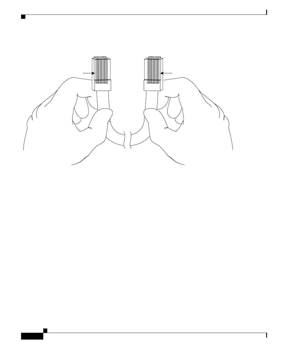
Figure B-5 Identifying a Rollover Cable
Console Port Mode 1 Signaling and Pinouts
This section provides the signaling and pinouts for the console port in mode 1
(CONSOLE PORT MODE switch in the in position).
DB-9 Adapter (for Connecting to a PC)
Use the RJ-45-to-RJ-45 rollover cable and RJ-45-to-DB-9 female DTE adapter
(labeled “Terminal”) to connect the console port to a PC running terminal
emulation software. Table B-5 lists the pinouts for the asynchronous serial
console port, the RJ-45-to-RJ-45 rollover cable, and the RJ-45-to-DB-9 female
DTE adapter.
Pin 1
Pin 8
H3824
Pin 1 and pin 8
should be the
same color
 Loading...


