B-13
Catalyst 6500 Series Switch Module Installation Guide
78-15725-02
Appendix B Cable and Connector Specifications
Supervisor Engine Console Port Signals and Pinouts
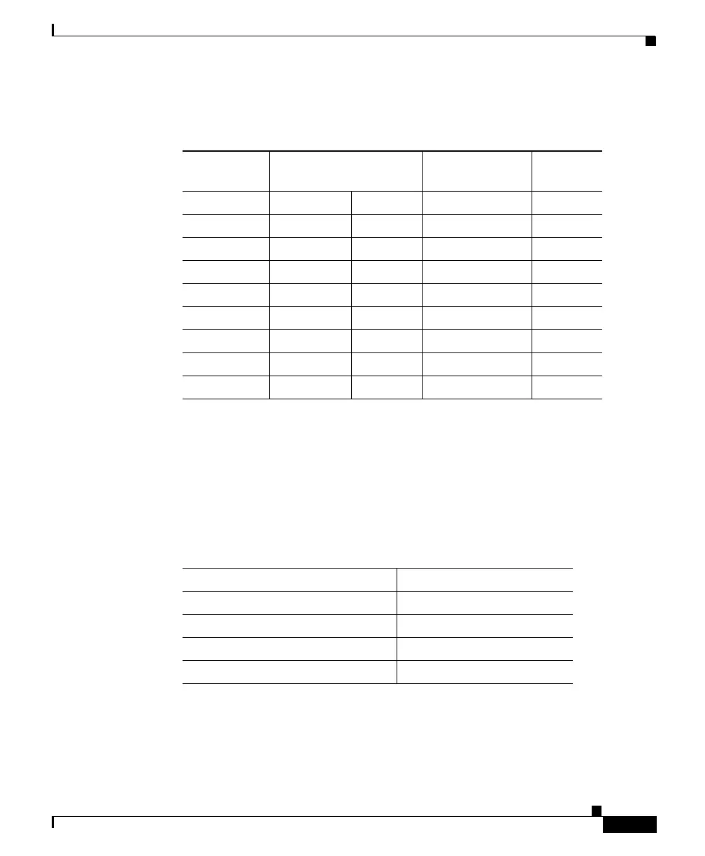
Console Port Mode 2 Signaling and Pinouts
This section provides the signaling and pinouts for the console port in mode 2
(console port mode switch in the out position). See Table B-8 for the pinouts.
Table B-7 Port Mode 1: Console Port Signaling and Pinouts
(Modem Adapter)
Console Port
RJ-45-to-RJ-45
Rollover Cable
RJ-45-to-DB-25
Modem Adapter Modem
Signal RJ-45 Pin RJ-45 Pin DB-25 Pin Signal
RTS 1
1
1. Pin 1 is connected internally to Pin 8.
84 RTS
DTR 2 7 20 DTR
TxD 3 6 3 TxD
GND 4 5 7 GND
GND 5 4 7 GND
RxD 6 3 2 RxD
DSR 7 3 8 DCD
CTS 8
1
15 CTS
Table B-8 Console Port Pinouts (Port Mode Switch Out)
Console Port Console Device
Pin (signal) Input/Output
1 (RTS)
1
Output
2 (DTR) Output
3 (RxD) Input
 Loading...


