Appendix B Cable and Connector Specifications
RJ-45 Connector
B-6
Catalyst 6500 Series Switch Module Installation Guide
78-15725-02
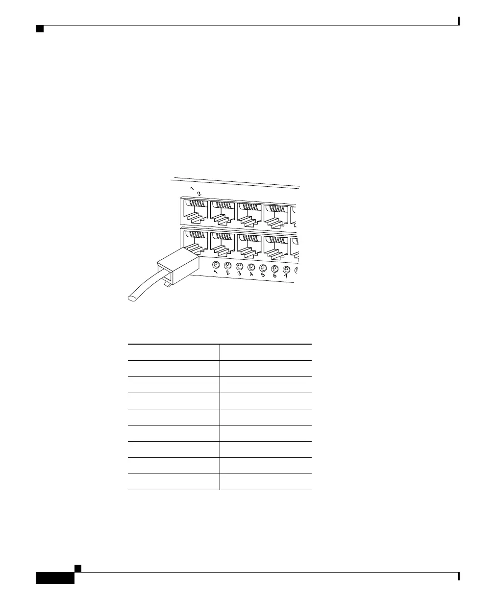
Inline power for IP Phones uses connector pins 1, 2, 3, and 6 in a Category 5,
Category 5e, or Category 6 cable to transmit power (6.3 W) from the switch. This
method of supplying power is sometimes called phantom power because the IP
Phone power travels over the same pairs of wires used to transmit the Ethernet
signals. The IP Phone voltage is completely transparent to the Ethernet signals
and does not interfere with their operation.
Figure B-2 RJ-45 Interface Cable Connector
Table B-3 10/100BASE-T Crossover Cable Pinout (MDI-X)
Side 1 Pin (Signal) Side 2 Pin (Signal)
1 (RD+) 3 (TD+)
2 (RD–) 6 (TD–)
3 (TD+) 1 (RD+)
6 (TD–) 2 (RD–)
4 (Not used) 4 (Not used)
5 (Not used) 5 (Not used)
7 (Not used) 7 (Not used)
8 (Not used) 8 (Not used)
48129
 Loading...


