Chapter 1 Product Overview
Switch Fabric Modules
1-74
Catalyst 6500 Series Switch Module Installation Guide
78-15725-02
Note The Switch Fabric 2 module cannot be installed in the Catalyst 6503 switch.
For redundancy, you can install a second Switch Fabric Module 2. The
first-installed Switch Fabric Module 2 functions as the primary module. When
you install two modules at the same time, the module in slot 5 or slot 7 functions
as the primary module, and the module installed in slot 6 or slot 8 functions as the
standby. If you reset the Switch Fabric Module 2 installed in slot 5 or slot 7, the
module in slot 6 or slot 8 becomes the primary.
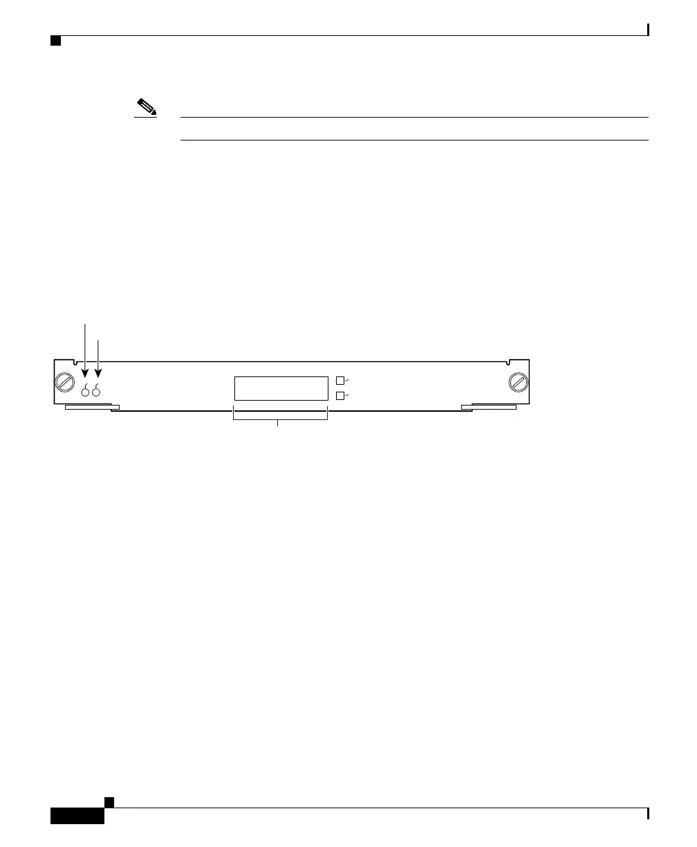
Figure 1-48 Switch Fabric Module 2 (WS-X6500-SFM2)
Two front-panel LEDs provide status information for the module and indicate
whether the module is active. The STATUS LED functions are listed in Table 1-6
on page 1-47. The ACTIVE LED is green when the Switch Fabric Module is
operational and active and is orange when the module is in standby mode.
The front panel of the Switch Fabric Module 2 has a 2-line by 20-character LCD
display. The display allows you to monitor the module’s input/outport port traffic
and local bus traffic. The display also shows system information.
Two push button switches control the LCD display:
• SELECT—This switch is used for LCD display menu selection.
• NEXT—This switch is used to scroll to the next item on the LCD display
menu.
51177
SWITCH FABRIC MDL
STA
TU
S
SE
LEC
T
N
EXT
WS-X6500-SFMIA
A
CTIVE
STATUS LED
ACTIVE LED
2 Line X 20 character
LCD display
 Loading...


