P2544PM | 2022-12 | REV H
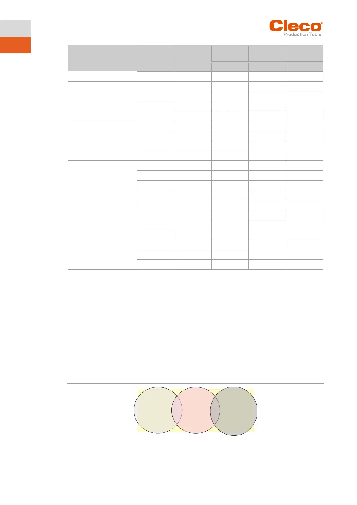
GHz
U‑NII‑1
U‑NII‑2
U‑NII‑2 ext
Legend
x: Approved and available
-: Not permissible, blocking necessary
o: Permissible with limited power to 20 dBm (SRD)
2.5.1.3 Cell planning for access point
Each channel operates with a frequency range of 22 MHz. To avoid overlapping the frequency ranges, the
channels must be chosen so that they do not overlap. In other words, a maximum of 3 independent chan-
nels (e.g., 1, 6 and 11) are available in the 2.4 GHz frequency band.
The 5 GHz frequency band provides up to 21 independent channels.
To minimize interference between different radio cells that share the same RF channel, it is advisable to
physically separate them. Note that for multistory buildings, it is necessary to consider both higher and
lower floors.
The following overview shows the basic channel assignment.
Fig. 2-5: Idealized radio cells, the rectangle symbolize the application areas of the tools
The physical circumference of a radio cell depends primarily on the access point used, the antennas and
the type of construction in the surrounding area. The limit of a radio cell is reached when the signal-to-
Channel 1
Channel 6
Channel 11