Mounting the machining arm
Page 36 CM6200 Operating Manual
Tighten the clamp bolts to 110 ft-lb (150 Nm) to prevent unexpected
movement that could cause serious injury or death.
The selector pin does not need to be engaged in a notch after the
turning arm adjustment. It is intended just to limit the turning arm’s
maximum amount of travel in the event that the turning arm comes
loose during operation.
Do not disable the safety stop pin. The safety stop pin is intended to
prevent unwanted shifting of the machining arm, which could result in
serious injury or death.
3.6.2 Repositioning the machining arm
The machining arm is incrementally adjustable for versatile positioning and to
clear obstructions.
Do the following to reposition the machining arm:
1. Loosen the screws holding the four clamps.
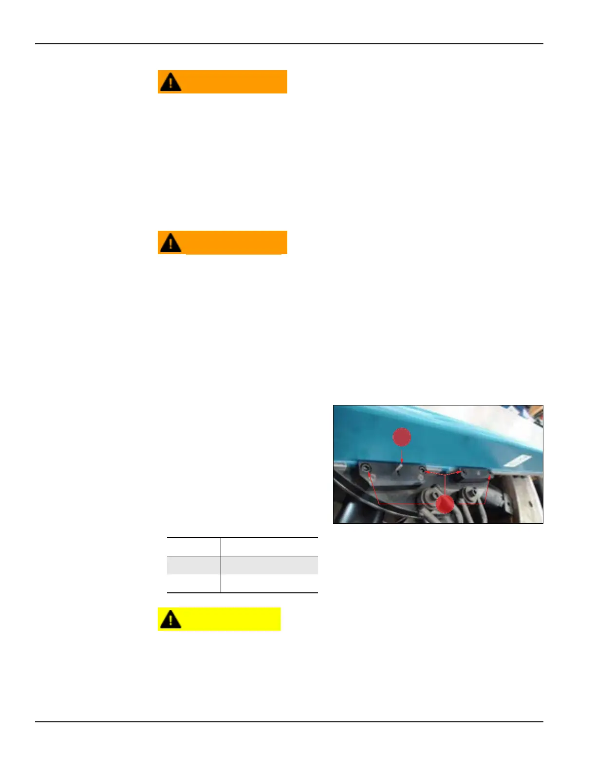
2. Hold the safety stop pin
open (Figure 3-19).
3. Slide the arm to the neces-
sary position.
4. Release the safety stop pin.
5. Re-tighten the clamps.
After adjusting the machining arm, make sure that the counterweight is
set to the corresponding bolt location increment.
For precise machining and to avoid damage to the machine, the
counterweight and machining arm should always be equally spaced
from the center of the machine.
TABLE 3-7. CLAMP SCREWS AND STOP
PIN IDENTIFICATION
Number Component
1 Stop pin
2 Clamp screws
FIGURE 3-19. CLAMP SCREWS AND STOP PIN