Installing machine on workpiece
Page 26 CM6200 Operating Manual
Do not extend the chuck feet jacking screws past the full-extension
groove in the threaded screw. If needed, add additional leg sections to
minimize the length of the threaded jacking screw that is exposed.
3.5 INSTALLING MACHINE ON WORKPIECE
3.5.1 Overview of CM6200 circular milling machine setup
Inspect and perform necessary maintenance on the machine before mounting on a
workpiece. The following steps are an overview of the processes involved with
setting up the CM6200 in the ID mounting configuration. The OD mount setup is
listed in Section 3.5.3 on page 33.
Do the following to mount the machine to the workpiece:
1. Check that power sources are disconnected.
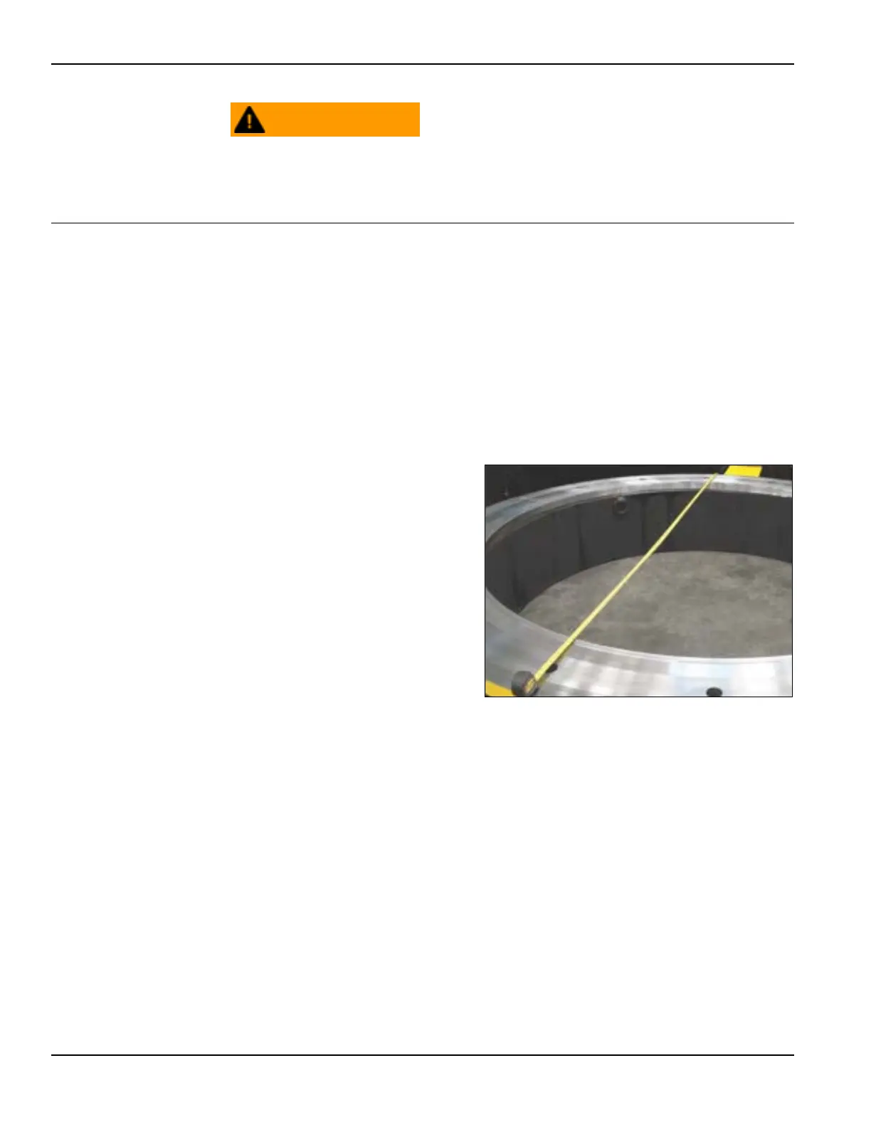
2. Measure the surface for
mounting and select proper
parts for machining, attach-
ing (customer-supplied)
scab plates or other mount-
ing surfaces as needed (Fig-
ure 3-6).
3. Before inserting the circu-
lar mill into the work piece,
confirm the legs are
securely attached to the
machine.
a) For ID mounting:
Confirm that the ID
mounting legs are set
to a diameter smaller than the internal mounting diameter.
FIGURE 3-6. MEASURE WORKPIECE