Mounting the machining arm
Page 38 CM6200 Operating Manual
To set the machine for a milling range, use the minimum and maximum of your
surface to determine the settings for the machining arm and counterweight, as
shown in Table 3-8.
3.6.3 Milling, grinding, or single-point setup
See Section 4.4 on page 81 for grinding configuration.
See Section 4.5 on page 82 for single-point configuration.
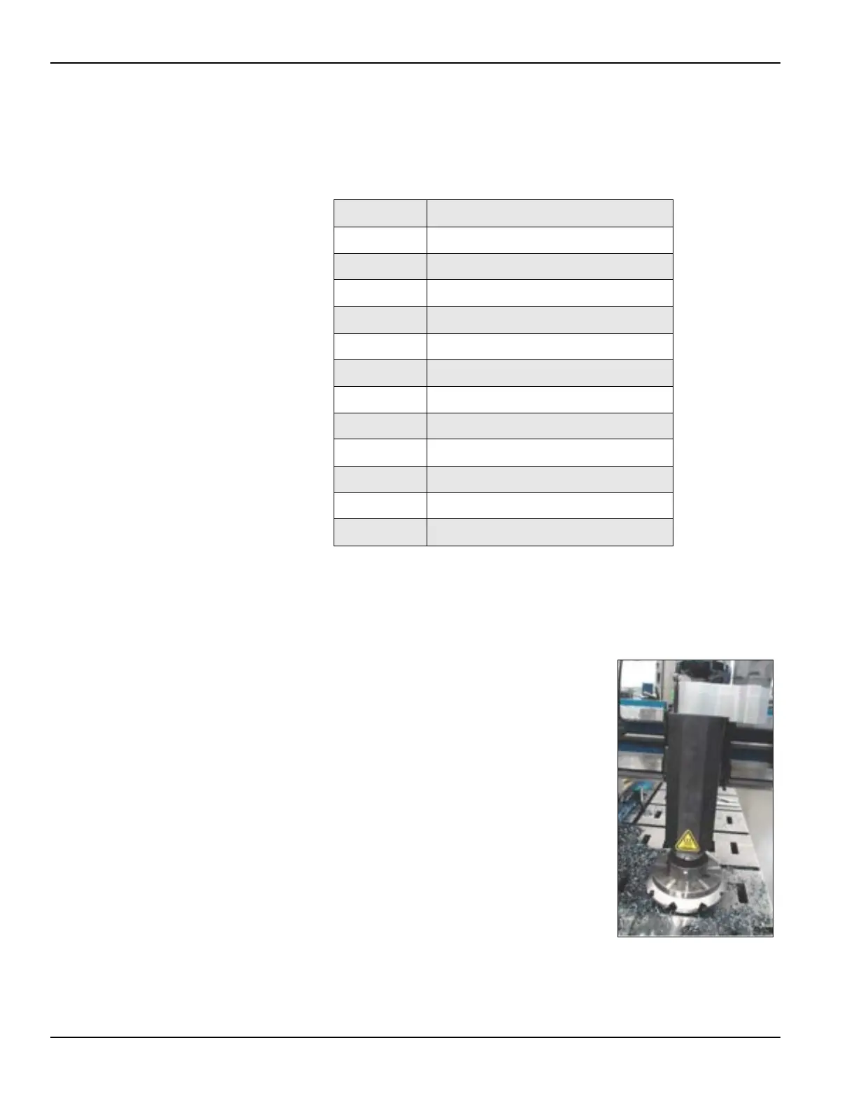
For milling, the milling head mounts to the CM6200
using an adapter plate.
Bolt-hole patterns in the adapter plate allow the milling
head assembly to be placed in 180° increments.
Before lifting the milling head assembly, determine
which alignment is required for machining operations.
Do the following to install the milling head:
1. Hoist the adapter plate into place and align.
2. Mount the adapter to the radial slide saddle and
bolt in place.
3. Align milling head plate to dowel pins in
adapter plate.
4. Remove all tools and lifting or rigging equip-
ment.
5. Check that all fasteners are tightened properly.
TABLE 3-8. POSITION OF MACHINING ARM AND COUNTERWEIGHT
Position Surface range in inches (mm)
1 123–73.5" (3,124.2–1,866.9 mm)
2 129–79.5" (3,276.6–2,019.3 mm)
3 135–85.5" (3,429.0–2,171.7 mm)
4 141–91.5" (3,581.4–2,324.1 mm)
5 147–97.5" (3,733.8–2,476.5 mm)
6 153–103.5" (3,886.2–2,628.9 mm)
7 159–109.5" (4,038.6–2,781.3 mm)
8 165–115.5" (4,191.0–2,933.7 mm)
9 171–121.5" (4,343.4–3,073.4 mm)
10 177–127.5" (4,495.8–3,238.5 mm)
11 183–133.5" (4,648.2–3,390.9 mm)
12 189–149.5" (4,800.6–3,797.3 mm)
FIGURE 3-22. INSTALLED MILL-
ING HEAD