Control pendant
P/N 63674, Rev. 9 Page 59
c) Adjust the X-axis
screws (where shown
in Figure 4-7) until the
indicator reads within
0.001" (0.03 mm).
7. Repeat the process of
sweeping the indicator at the
0° and 180° locations and
adjusting the spindle orien-
tation until the same read-
ing is achieved at both
locations.
8. Once both axes are within
tolerance, tighten the mount-
ing bolts to 45 ft-lbs (61
Nm).
Keep the dial indicator installed during the final tightening of the
mounting screws, so you can recheck that the housing does not move
during tensioning.
9. Reinstall the spindle drive motor (if necessary).
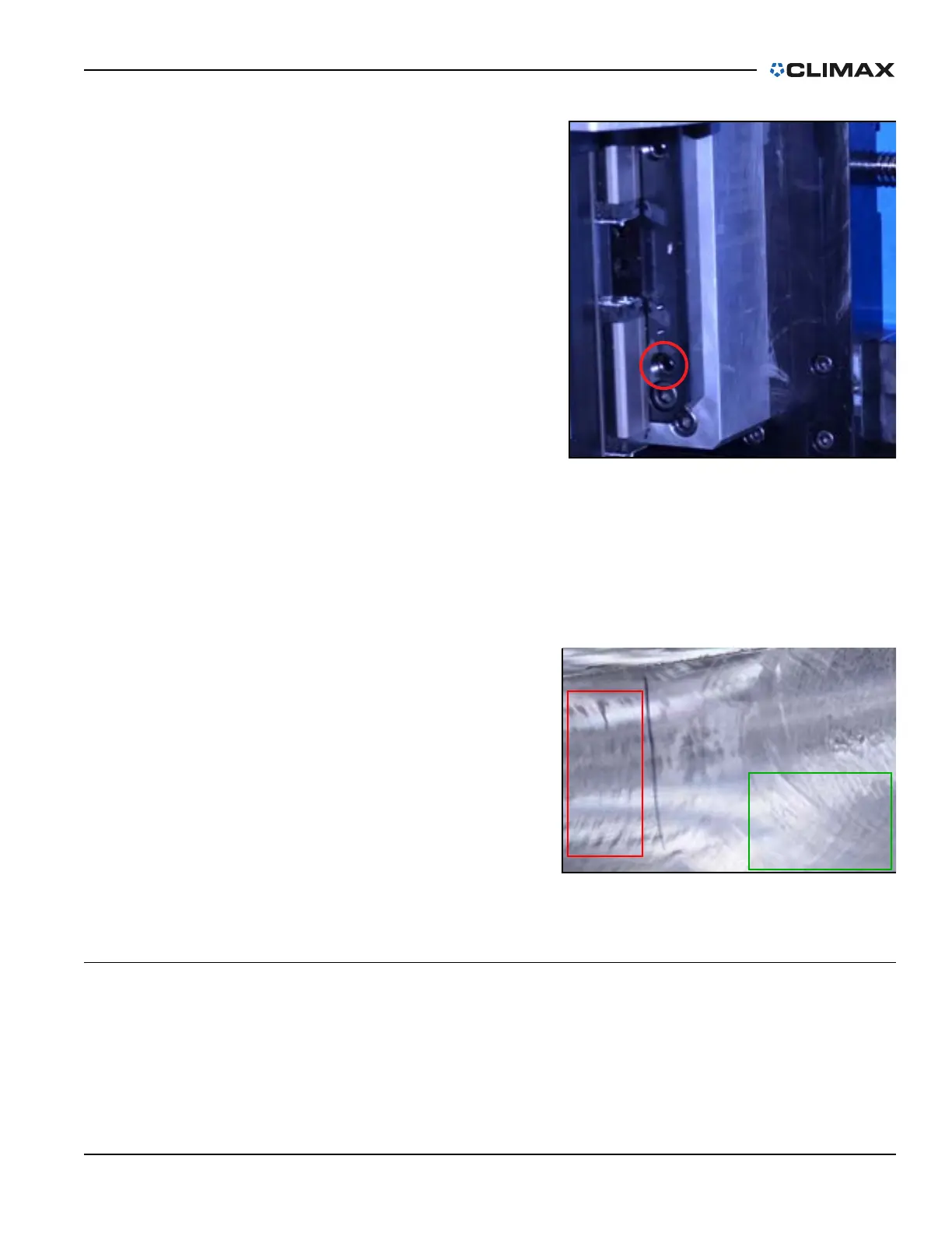
When ready to operate the machine,
note the machined surface after the
first pass.
A crosshatched pattern is the opti-
mal result, as shown in the right of
Figure 4-8.
If the results are heel-edged, as
shown in the left of Figure 4-8,
adjust the X-axis screws according
to step c on page 59.
4.2 CONTROL PENDANT
4.2.1 Coordinate systems
This machine has two separate coordinate systems that track the position of the
machine. The zero point can be reset at any time on either of the coordinate sys-
tems without affecting the position in the other system.
FIGURE 4-7. X-AXIS SCREW LOCATION
FIGURE 4-8. MACHINING PASS RESULTS