Operation setup
Page 58 CM6200 Operating Manual
There are two cap screws on each side of the milling head, which is
mounted in the center of the tramming plate shown in Figure 4-5.
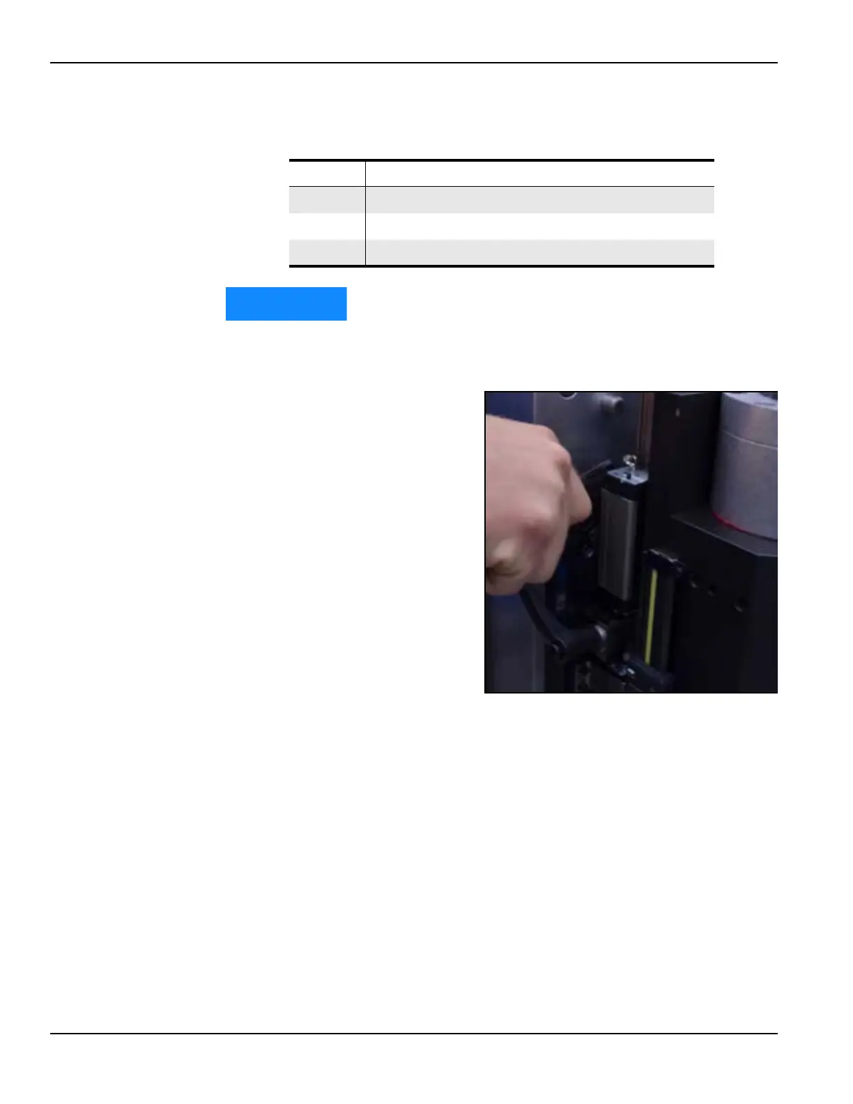
b) Adjust the Y-axis
screws until the indica-
tor reads within 0.001”
(0.03 mm). See Figure
4-6.
TABLE 4-1. MILLING HEAD MOUNTING PLATE IDENTIFICATION
Number Component
1 Y-axis tramming points rotation
2 Loosen first
3 X-axis tramming point
FIGURE 4-6. Y-AXIS SCREW ADJUSTMENT