Circular milling
Page 76 CM6200 Operating Manual
4.3.1 Installing the milling head cutter
Do the following to install the milling head cutter:
1. Check that the cutter is sharp and free of nicks.
2. Check that the spindle is completely stopped and machine power is locked
out.
3. Clean dirt and chips from the spindle taper surface.
4. Insert the cutter into the spindle. Be sure the cutter is engaged with the
drive lugs.
5. Install the draw bolt to secure the cutter into the spindle.
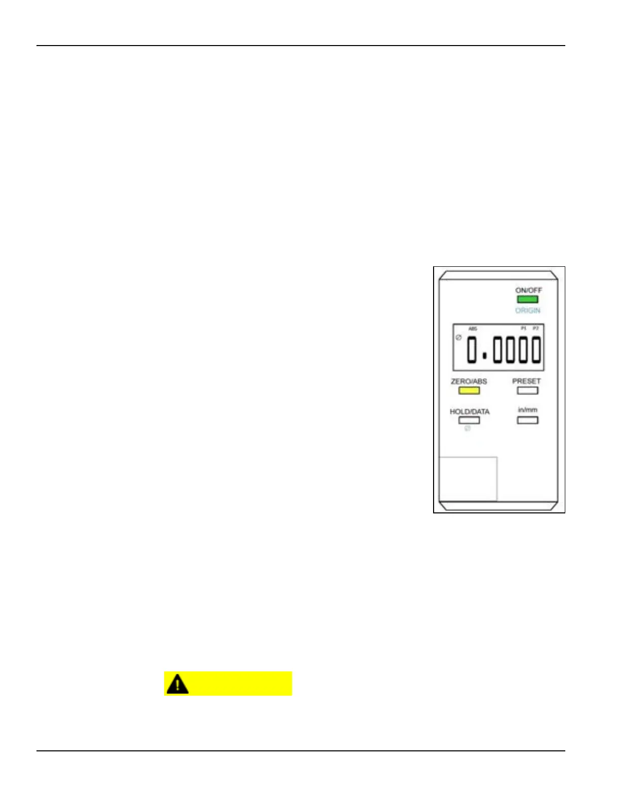
4.3.2 Setting the DRO (milling head equipment)
For most operations, simply turn on the DRO and
press the ZERO/ABS button to zero the display
before making any adjustments to the milling head.
The DRO will display the correct distances in the
digital readout (see Figure 4-28).
4.3.3 Safe operating ranges
Table 4-2 on page 77 shows the surface feet per minute (sfpm) and surface meters
per minute (smpm) for a given tool diameter and hydraulic motor size at 60 Hz and
20 gallons per minute (gpm) or 76 liters per minute (lpm). Table 4-3 on page 78
shows the same information at 50 Hz and 16.6 gpm (63 lpm).
Do not pick a motor and tool combination that is less than 150 sfpm
(45.72 smpm) at 20 gpm (76 lpm). The resulting peak force at the cutter
FIGURE 4-28. DRO BUTTONS AND
DISPLAY