Installing machine on workpiece
P/N 63674, Rev. 9 Page 29
3.5.2 ID mount leg assembly
The highlighted items in Figure 3-
10 are 4”-4UN triple lead threaded.
The leveling chuck feet jaws
include clamps for internal flanges
up to 8" (210 mm).
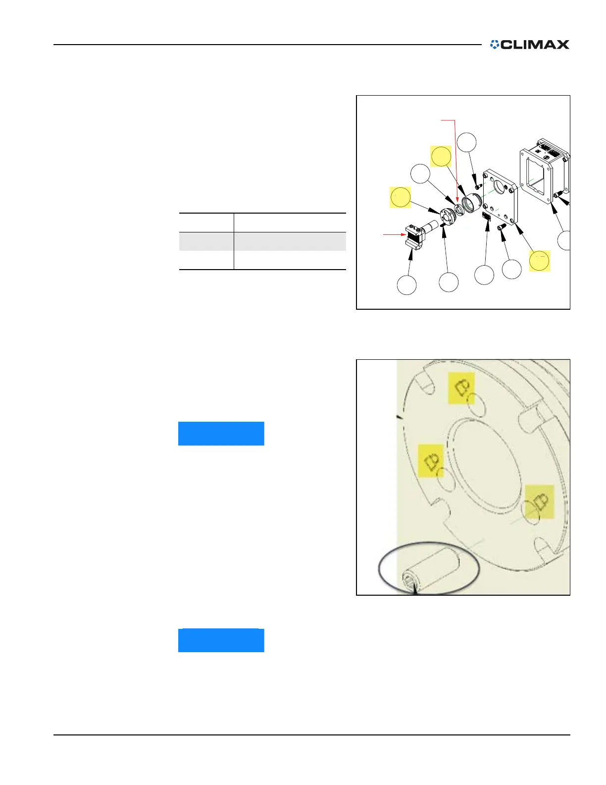
On the end cap, the highlighted
lock symbols are for the jacking
screw locking system (see Figure
3-11).
After the final adjustments
are complete on the chuck
feet, tighten one of the three
socket head set screw (P/N
74499 M12 x 40mm long to
29 ft-lbs (40 Nm) (shown
circled in Figure 3-11) to lock
the jacking screw position.
Loosen this screw before
making additional jacking
adjustments—or removing
the machine from the flange.
The chuck legs will alternate high and low around the hub for double
plane. For single plane, the jacking screws will normally all be mounted
high.
TABLE 3-2. LOCKING NUT AND LEVELING
JAW IDENTIFICATION
Number Component
1 Internal locking nut
2 Leveling jaw
FIGURE 3-10. LOCKING NUT AND LEVELING JAW
1
1
FIGURE 3-11. LOCKING SYMBOLS ON END CAP