Installing machine on workpiece
Page 30 CM6200 Operating Manual
Use supplemental rigging, such as setup fingers, when mounting the
machine, in case it falls out or through the chucking diameter.
The rotary table can be set up in the ID or the optional OD configuration. An ID
configuration allows mounting internally on a flange. An OD configuration allows
attaching the machine to the outside of a flange. See Section 4.5.1 on page 84.
The double-plane setup in the ID configuration uses alternating legs so that the
leveling legs are higher than the non-leveling legs. This arrangement may provide
additional stability to the machine, depending on the nature of the workpiece.
If the workpiece will not accommodate the double-plane setup, then
other methods for increasing stability of the machine should be used.
See Section 3.5.3 on page 33 for attachment methods.
Do the following to set up the rotary table mounting feet:
1. Measure the workpiece bore.
2. Select the appropriate parts for assembly.
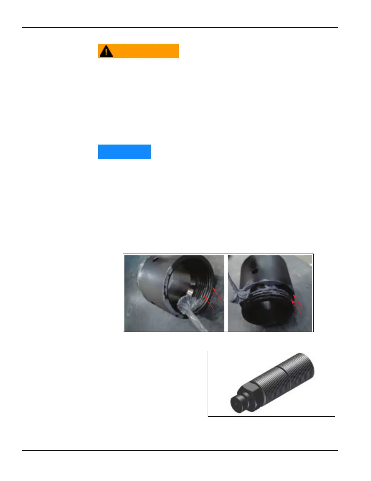
3. Apply anti-seize (provided in the tool kit) to the following locations:
• The threads and contacting faces of each chuck extension leg section,
as shown in Figure 3-12.
FIGURE 3-12. LOCATIONS TO APPLY ANTI-SEIZE
• The jacking screw
threads, to prevent
thread galling (Figure 3-
13.)
FIGURE 3-13. JACKING SCREW