Mounting machine to workpiece
Page 40 CM6200 Operating Manual
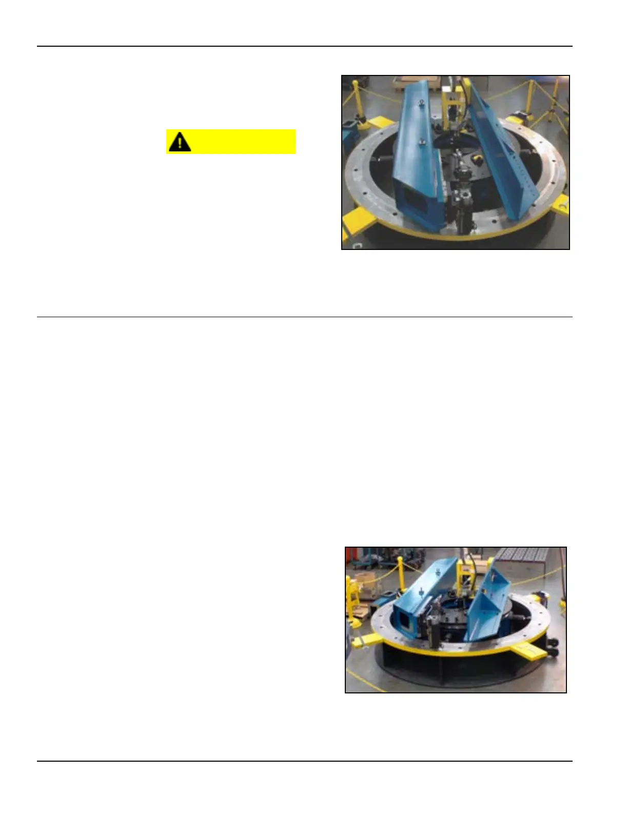
2. Bolt the counterweight
securely into place (Fig-
ure 3-24).
For precise machining and
to avoid damage to the
machine, the
counterweight and
machining arm should
always be equally spaced
from the center of the
machine. The location
numbers should be the
same.
3.8 MOUNTING MACHINE TO WORKPIECE
Once the chuck feet are correctly configured and attached to the chuck, the
machine is ready to be mounted to the workpiece.
See Section 3.4 on page 25 for a full list of installation hazards.
3.8.1 ID mounting the machine horizontally
Do the following to ID mount the machine to a horizontal flange:
1. Set the ID mounting chuck feet to a dimension that is 0.01" (0.25 mm) less
per leg than the dimension of the inner diameter of the workpiece.
2. Position the machining arm (see Section 3.6 on page 35) and the counter-
weight arm (see Section 3.7 on page 39) before lifting (see Section 3.3 on
page 22).
3. Lift the machine into the
inner diameter of the
workpiece—using the
four hoist rings on the top
hub (as shown in Figure
3-2 on page 23).
4. Extend the chuck feet at
the 6:00, 9:00, 12:00, and
3:00 positions to secure
the machine into position.
FIGURE 3-24. COUNTERWEIGHT AND MACHINING ARM ON THE
ROTARY TABLE
FIGURE 3-25. HORIZONTALLY MOUNTED MACHINE