Fixation of ID mount
Page 48 CM6200 Operating Manual
a) For ID, adjust the lev-
eling screws in each
of the leveling chuck
feet (see Figure 3-35).
b) For OD, adjust the leveling set screws above the centering plate (see
Figure 3-26 on page 41).
3. Reposition the dial indicator to check machine centering.
4. Center the machine by doing the following:
a) For ID, adjust the opposing pairs of chuck feet (one foot shown in
Figure 3-35).
b) For OD, adjust the centering set screws in the centering plate (see
Figure 3-26 on page 41).
5. Check the machine for level and center again.
6. Repeat step 2 through step 6 until the machine is aligned.
7. Fix the machine in place according to Section 3.10 on page 48 (for ID) and
Section 3.5.3 on page 33 (for OD).
8. Recheck machine alignment. If any adjustments are necessary, repeat "Fix-
ation of ID mount" on page 48 (for ID) and Section 3.5.3 on page 33 (for
OD).
9. Mark the high point of the flange so that the initial milling depth can be set
at this point.
10. Remove any rigging.
3.10 FIXATION OF ID MOUNT
In ID configurations, the CM6200 is held in the workpiece by friction force from
torquing eight chuck feet jacking screws.
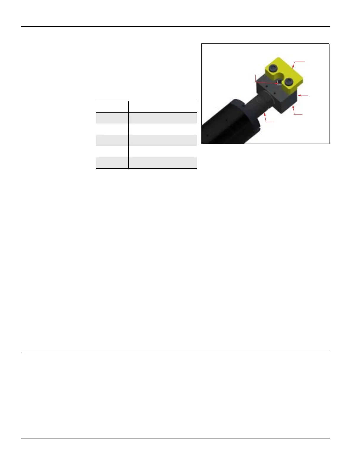
TABLE 3-11. LEVELING CHUCK FOOT
IDENTIFICATION
Number Component
1 Set-up finger
2 Jaw adjuster
3 Base adjuster
4 Jacking bolt
5 Leveling screw
FIGURE 3-35. LEVELING CHUCK FOOT ASSEMBLY