Installing machine on workpiece
P/N 63674, Rev. 9 Page 31
4. Refer to the exploded view drawings Figure A-7 on page 126, Figure A-8
on page 127, and Figure A-9 on page 128, Table 3-5 on page 32 and
Table 3-6 on page 34 when assembling the chuck legs.
5. The chuck legs will alternate high and low around the hub. Secure the
chuck arms to the hub with the bolts supplied.
6. After attaching the end cap to the chuck extensions leg, install the leveling
and non-leveling chuck feet assemblies. The leveling chuck feet must be
mounted to the four upper leg end caps. The non-leveling chuck feet must
be mounted to the lower leg end caps.
7. Secure the chuck arms to the hub with the bolts supplied.
8. After attaching the end cap to the chuck extensions leg, install the leveling
chuck feet assemblies.
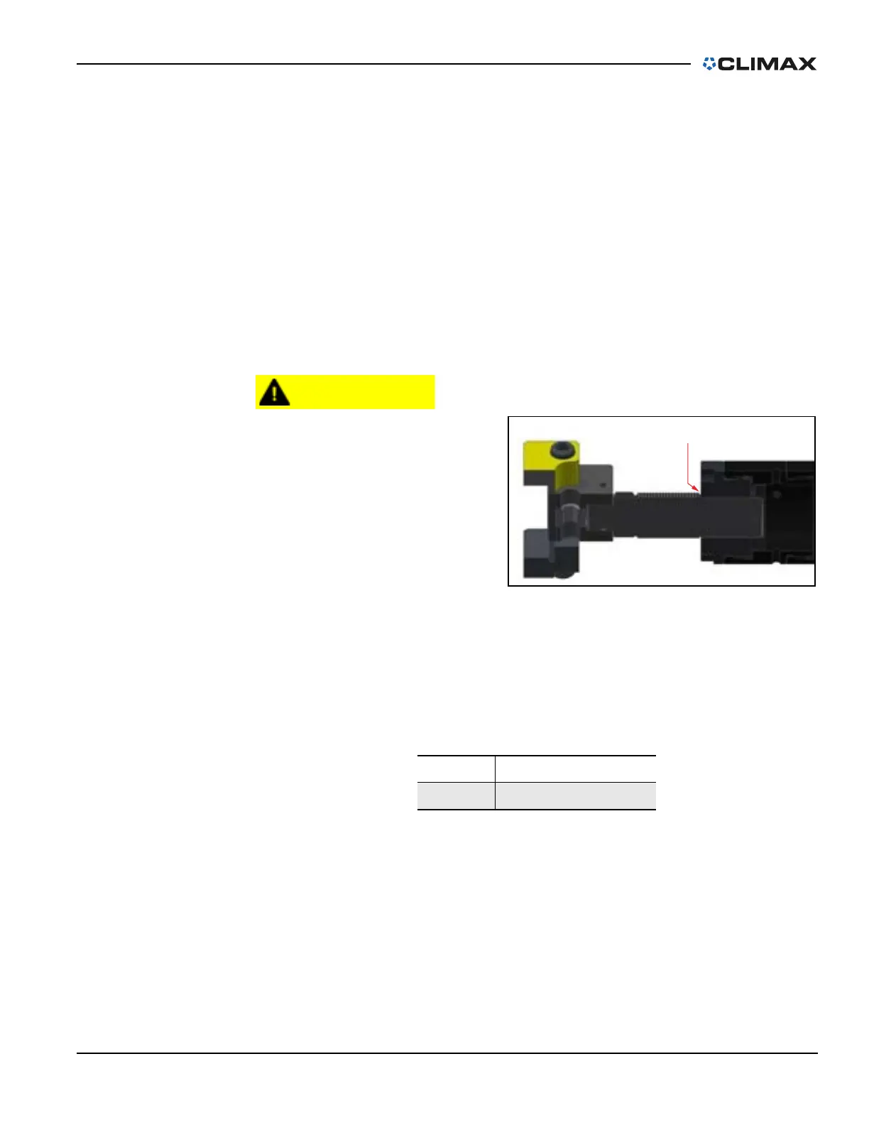
The jacking screw must be
inserted so that the full
extension groove is inside
the end cap.
Do not extend the jacking
feet past the full-extension
groove in the threaded
screw (Figure 3-14), as that
may overload the jacking
screw and result in damage
to the screw.
If needed, add additional leg sections to minimize the length of the
threaded jacking screw that is exposed.
TABLE 3-3. JACKING SCREW GROOVE IDENTIFICATION
Number Component
1 Jacking screw groove
FIGURE 3-14. JACKING SCREW GROOVE (LEVELING FOOT)
1