Installing machine on workpiece
Page 32 CM6200 Operating Manual
9. Adjust the jacking bolts
equally until they are
approximately 3/8" (10
mm) less than the work-
piece inside diameter.
10. Install the setup fingers
onto the leveling blocks.
Adjust the fingers so they will rest on the workpiece flange.
Before putting the chuck onto the workpiece, check that the jacking
screws are roughly equally retracted and equipped with the set-up
fingers.
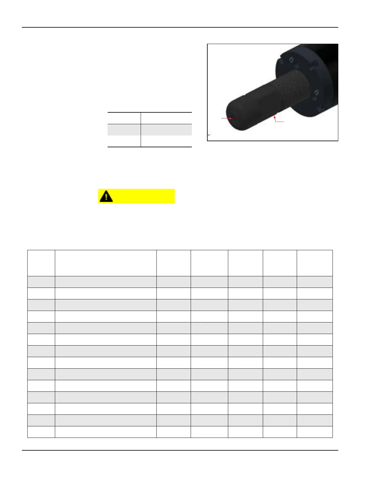
TABLE 3-4. NON-LEVELING JACKING
FOOT IDENTIFICATION
Number Component
1 Gripper pad
2 Jacking bolt
FIGURE 3-15. NON-LEVELING JACKING FOOT
TABLE 3-5. ID CHUCKING LEG SETUP SPECIFICATIONS
Range Workpiece inside diameter
12.5"
(318 mm)
standoff
17.5"
(445 mm)
standoff
27.5"
(699 mm)
standoff
2.5"
(64 mm)
leg
5"
(127 mm)
leg
1 78.9–83.9" (2,004–2,131 mm)
a
0 0 0 0 0
2 83.9–88.9" (2,131–2,285 mm) 0 0 0 1 0
3 88.9–93.9" (2,285–2,385 mm) 0 0 0 0 1
4 93.9–98.9" (2,385–2,512 mm) 0 0 0 1 1
5 98.9–103.9" (2,512–2639 mm) 0 0 0 0 2
b
6 103.9–108.9" (2,639–2,766 mm) 1 0 0 0 0
7 108.9–113.9" (2,766–2,893 mm) 1 0 0 1 0
8 113.9– 118.9" (2,893–3020 mm) 0 1 0 0 0
9 118.9–123.9" (3,020–3,147 mm) 0 1 0 1 0
10 123.9–128.9" (3,147–3,274 mm) 0 1 0 0 1
11 128.9–133.9" (3,274–3,401 mm) 0 1 0 1 1
12 133.9–138.9" (3,401–3,528 mm) 0 0 1 0 0
13 138.9–143.9" (3,528–3,655 mm) 1 1 0 0 0
14 143.9–148.9" (3,655–3,782 mm) 1 1 0 1 0