Installing machine on workpiece
Page 34 CM6200 Operating Manual
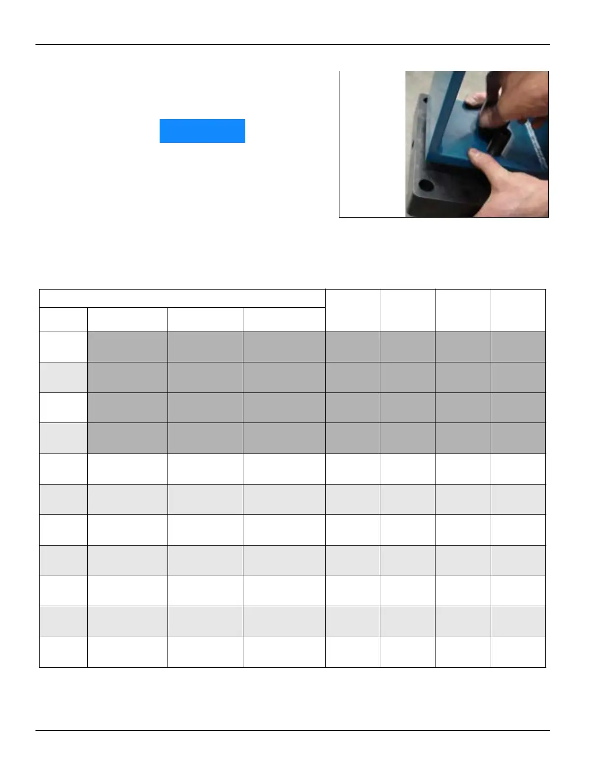
3. Attach the centering plate
onto the ends of each OD
mount leg (Figure 3-17).
In Table 3-6, the first four
rows highlighted in dark gray
are not practical because of
the minimum arm swing
length. See Figure 3-18 on
page 35.
FIGURE 3-17. OD MOUNT CENTERING PLATE
TABLE 3-6. OD CHUCKING LEG SETUP CHART
Diameter 12.5"
(318 mm)
standoff
17.5"
(445 mm)
standoff
27.5"
(699 mm)
standoff
5"
(127 mm)
leg
Range A
a
B
b
C
c
1
92.5"
(2,350 mm)
102.38"
(2,600 mm)
110.4"
(2,804 mm)
1 0 0 0
2
102.5"
(2,604 mm)
112.38"
(2,854 mm)
120.4"
(3,058 mm)
0 1 0 0
3
112.5"
(2,858 mm)
122.38"
(3,108 mm)
130.4"
(3,312 mm)
0 1 0 1
4
122.5"
(3,112 mm)
132.38"
(3,362 mm)
140.4"
(3,566 mm)
0 0 1 0
5
127.5"
(3,239 mm)
137.38"
(3,489 mm)
145.4"
(3,693 mm)
1100
6
137.5"
(3,493 mm)
147.38"
(3,743 mm)
155.4"
(3,947 mm)
1 1 0 1
7
147.5"
(3,747 mm)
157.38"
(3,997 mm)
165.4"
(4,201 mm)
1010
8
157.5"
(4,001 mm)
167.38"
(4,251 mm)
175.4"
(4,455 mm)
1 0 1 1
9
167.5"
(4,255 mm)
177.38"
(4,505 mm)
185.4"
(4,709 mm)
0111
10
182.5"
(4,636 mm)
192.38"
(4,886 mm)
200.4"
(5,090 mm)
1 1 1 0
11
192.5"
(4,890 mm)
202.38"
(5,140 mm)
210.4"
(5,344 mm)
1111
a. A is measured from mounting face to mounting face of the vertical supports.
b. B is the swing clearance inside the vertical supports for the machining arm.
c. C is measured from center of mounting plate to center of mounting plate.