Operation setup
P/N 63674, Rev. 9 Page 57
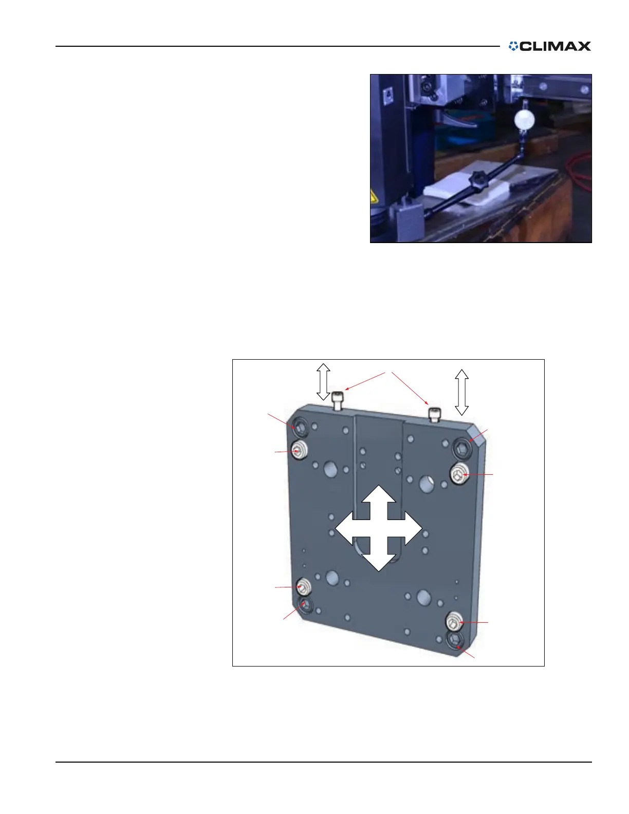
5. Rotate the spindle 180° to
the machine ram surface
(see Figure 4-4).
With the standard spindle,
the angle is limited to ±1°. If a
greater angle is needed, a
swivel head adapter will be
needed. For further
information, contact CLIMAX.
6. Note the dial reading. If it is
more than 0.001" (0.03 mm)
out of tramming tolerance,
do the following:
a) Loosen the four cap screws so that they are just slightly snug
(between 1–3 ft-lb ([1–4 Nm]), as shown in Figure 4-5, so that the
tramming setscrews can adjust the plate.
FIGURE 4-5. MILLING HEAD MOUNTING PLATE AND TRAMMING POINTS
FIGURE 4-4. SPINDLE ROTATED TO THE RAM SURFACE