Installing machine on workpiece
P/N 63674, Rev. 9 Page 27
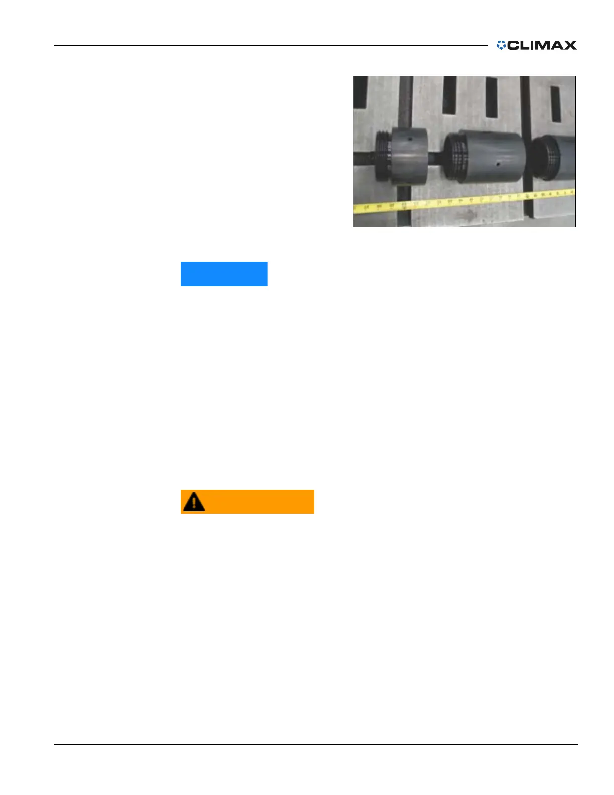
b) For OD mounting:
Confirm that the OD
mounting legs are
set to a diameter
larger than the
flange diameter
(Figure 3-7). See
Section 3.5.2 on
page 29 and
Section 3.5.3 on
page 33 for the com-
plete procedure for
chuck leg setup.
If mounting the CM6200 in the vertical position, then the machining arm
and counterweight should be attached to the rotary table (step 5) before
mounting the machine to the workpiece (step 8).This will reduce the
possibility of an unintentional rotational shift during the installation
process.
4. Position the counterweight and machining arm in location slots that are
equidistant from the machine center, with the same location number, in
order to balance the machine.
5. Secure the machining arm and counterweight to the rotary table. See
Section 3.6 on page 35 and Section 3.7 on page 39 for specific torque val-
ues.
6. Attach the crane slings to the lifting points on the rotary table.
Only use individual slings for each hoist rings and be sure that they are
of appropriate and equal length, and rated for the machine weight, and
sling angle.
7. Lift the machine slowly and carefully. If it is out of balance, lower the
machine to the ground. Make adjustments before attempting to lift and
maneuver it again.
FIGURE 3-7. LEG MEASUREMENT