Page 32 FF6300 Operating Manual
3.6 INSTALLING THE ID CHUCK IN THE WORKPIECE
See Section Section 3.5 on page 30 for a full list of installation hazard warnings.
The machine ships with the main body mounted to the ID chuck. See Section 3.7 on
page 36 for OD mounting or Section 3.8 on page 42 for surface mounting.
The FF6300 ID chuck can be removed from the main body rotating assembly. The
chuck can be installed independently as a subassembly when there are access or
rigging constraints. It can also remain attached to the main body during the machine
installation.
Use supplemental rigging when mounting the machine, in case it falls out
or through the chucking diameter.
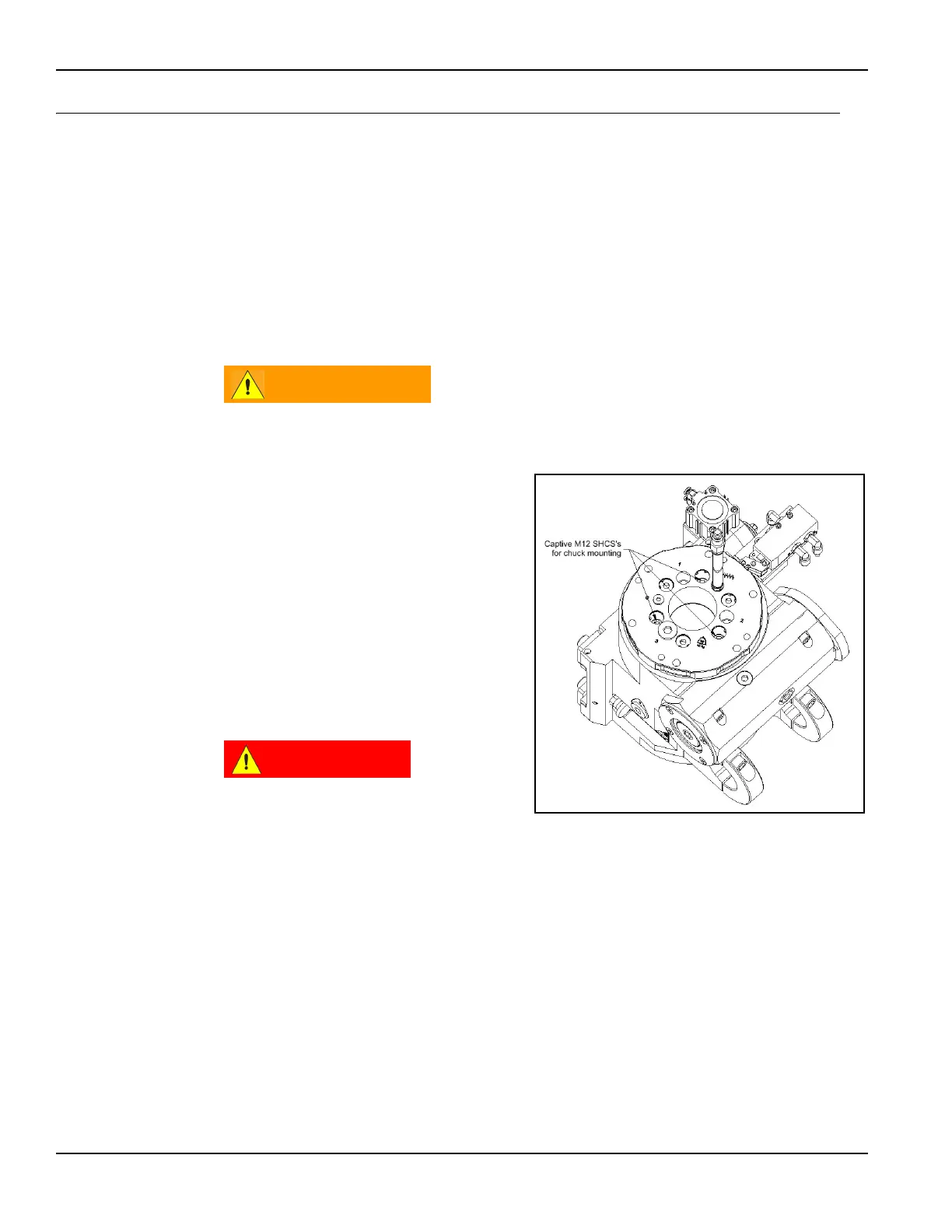
The ID chuck hub is attached to the
main body by three M12 through-bolts
that pass through the main machine
spindle (Figure 3-10).
Because the ID chuck secures the
machine to the workpiece, it is very
important that the chuck be securely
clamped into position. Common appli-
cations include both flange faces that
are horizontal (on the same plane as
the floor or overhead) or vertical.
Whenever there is a possibility
of the machine falling out of or
through the chucking diameter,
take special care to check that
the ID chuck is secure before releasing the rigging.
FIGURE 3-10. ATTACHING THE ID CHUCK TO THE MAIN BODY