Page 28 FF6300 Operating Manual
The machine can be broken down quickly into more manageable sections if needed.
3.4 SETUP OVERVIEW FOR THE ID CHUCK MACHINE
Inspect and perform necessary maintenance on the machine before mounting on a
workpiece. The following steps are an overview of the processes involved with setting
up the FF6300 in the ID mounting configuration. The OD mount setup is listed in
Section 3.7 on page 36
To set up the FF6300 ID chuck, follow the process below. For details on these steps,
see Section 3.6 on page 32 through Section 3.12 on page 48.
To mount the machine to the workpiece:
1. Check that power sources are disconnected.
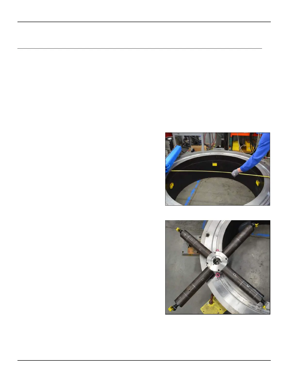
2. Measure the bore diameter. Use
the setup chart in Table 3-1 on
page 33 to select leg sections of
the correct length.
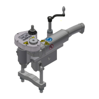
3. Assemble the ID chuck (Figure
3-3).
FIGURE 3-2. MEASURE THE FLANGE
FIGURE 3-3. ASSEMBLE THE ID CHUCK