Page 40 FF6300 Operating Manual
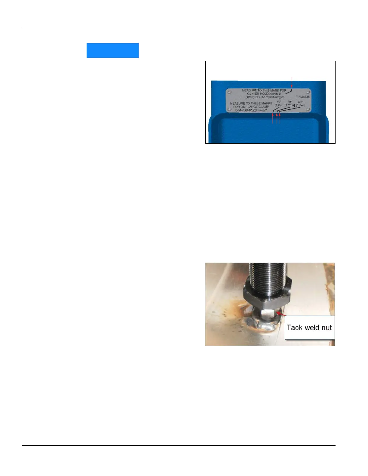
Referring to Figure 3-21:
measure to the top point for the
dimension to the center of the
16-mm rod.
Swing the tape measure to the
appropriate bottom point to
align with the actual OD for the
chain clamp.
Example for arrangement B: In order
to chain clamp to a flange that is 55"
(1,397 mm), calculate the following:
1. 55" – 9" = 46"
2. 46" / 2 = 23"
3. Adjust two of the legs to 23".
4. Adjust the third leg to 23.25".
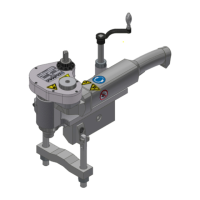
3.7.4 Attaching the OD mount assembly to the workpiece
The OD mount vertical legs attach to the workpiece with a single M16 x 2.0 all-thread
rod at each leg. There are numerous ways to mount the machine to the workpiece.
Three possible ways to attach the OD mount assembly to the workpiece are:
• Attach the vertical legs by
tack-welding an M16 nut to
the workpiece. Use a mini-
mum of a 3/16" (4.76 mm)
weld x 1" (25 mm) long
(Figure 3-22).
• Attach the vertical legs by
clamping a plate with an
M16 threaded hole to the
workpiece at each mount-
ing point.
POINT FOR
ARRANGEMENT A
POINTS FOR
ARRANGEMENT B
FIGURE 3-21. MEASUREMENT POINTS FOR EACH ARRANGE-
MENT
FIGURE 3-22. ATTACHING THE OD MOUNT WITH A TACK-WELD
NUT