Page 66 FF6300 Operating Manual
5.3.8 Adjust the dovetail and square ways gib screws
Adjusting the dovetail slide on the tool head is done using five M6 x 1.0 gib screws.
For screw locations, see Figure A-6 on page 86.
Adjusting the square ways on the turning arm is done using three M6 x 1.0 gib screws.
For screw locations, see Figure A-10 on page 90.
The radial slide (square way gib screws) must be snug for the best cutting perfor-
mance. Approximately 2–4 in-lbs (.3 Nm) of torque is necessary to turn the radial
travel leadscrew.
Adjustment should be necessary only after many hours of use and only if the machine
is no longer producing a good finish.
If a slide is visibly loose and causing machining problems, tighten the gib screws in
small increments. There should be 2–4 in-lbs (.3 Nm) of drag on the radial leadscrew
and a slight drag on the manual feed handle.
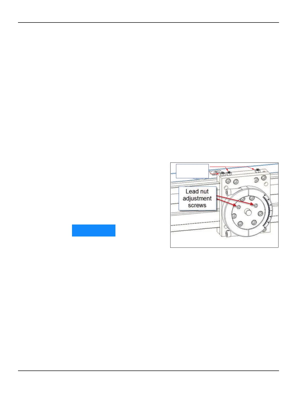
5.3.9 Adjust the radial slide lead nut
The radial slide lead nut is adjustable
to provide reduced backlash. Adjusting
the lead nut is done using two M10 x
1.50 set screws recessed in the swivel
circular dove plate. Adjustment should
be necessary only after many hours of
use and only if the machine is no
longer producing a good finish.
Only adjust the radial slide lead
nut after adjusting the square
way gibs, as described in
Section 5.3.8.
If the slide is visibly loose and causing machining problems, tighten the two set screws
by small increments until a slight drag is felt on the manual feed handle.
After adjustment, check travel over the full length of the leadscrew for tight spots.
5.3.10 Tram the turning arm
Do the following if the turning arm becomes misaligned:
1. The bottom surface of the main body assembly can be used as a datum
(Figure 2-1 on page 15 and Figure A-8 on page 88).
2. Tighten the two M8 screws (number 49 in Figure A-8 on page 88) on the top of
the main body assembly, and then back them off a little.
FIGURE 5-1. LOCATION OF LEAD NUT ADJUSTMENT SCREWS