Page 38 FF6300 Operating Manual
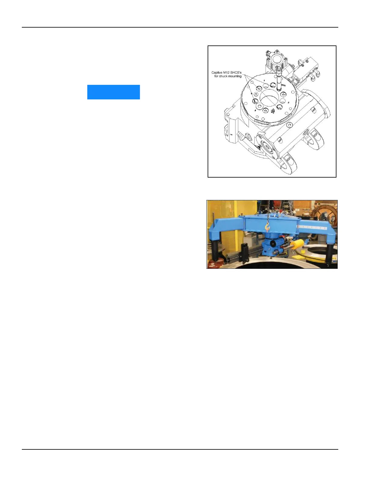
7. Install three M12 nuts on the
captive chuck mounting bolts
and tighten to 50 ft-lbs
(68 N m).
Failure to install and torque
these nuts may lead to poor
machine performance.
8. Set the FF6300 machine on the
ground on wooden blocks.
9. Remove any lifting eyes from
the top of the main body
assembly.
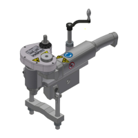
10. Using the three lifting eyes on
the OD mount, lift the OD
mount into place on top of the
machine. Use care when
threading the hoses through the
hole in the center of the OD
mount so that the hoses are not
ped or damaged.
11. Install the six M12 fasteners
and tighten to approximately
50 ft-lbs (68 N m).
12. Screw the leg sections into the radial extension legs.
13. The radial legs are adjustable. Adjust the legs to the desired mounting diame-
ter. See Section 3.7.3 on page 38 for available mounting arrangements.
14. Tighten the 12 leg clamping bolts to 35 ft-lbs (47 N m).
3.7.3 OD mounting arrangements
There are two mounting arrangements (described further in Section 3.7.4 on page 40):
• Arrangement A attaches the OD mount to the workpiece using the M16
threaded rod to either a tack-welded nut, holes in the workpiece, or other
available feature. The key dimension is the diameter to the centerline of
where the M16 rod will attach.
• Arrangement B attaches the OD mount to the OD chain clamps and clamps
them to the OD of the workpiece. The key dimension is the outside dimen-
sion to which the clamps will attach.
FIGURE 3-18. ATTACHING THE OD MOUNT ASSEMBLY TO THE
MAIN BODY
FIGURE 3-19. OD MOUNT ASSEMBLY