P/N 80679, Rev. 10 Page 39
Arrangement A
Do the following for arrangement A:
1. Subtract 15" (381 mm) from the key dimension. Divide the difference by two.
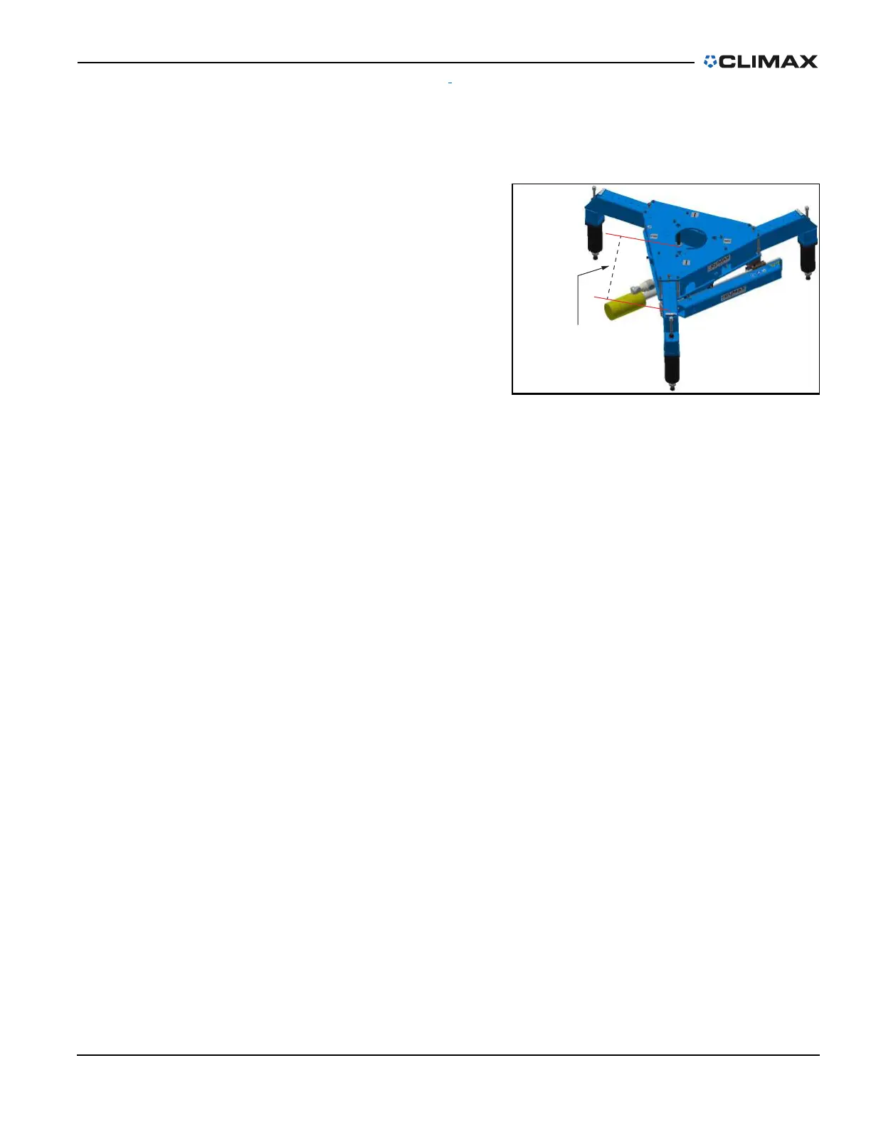
2. Hook the tape measure to the
interior 9" (228 mm) diameter
hole on the top plate of the OD
mount (see Figure 3-20).
3. Adjust the leg until the dimen-
sion to the top of the end leg
label equals the calculated
result.
Example for arrangement A: In order
to mount the OD mount to the three
existing M16 holes on the workpiece
that are on a 60.5" (1,537 mm) bolting
circle, calculate the following:
1. 60.5" – 15" = 45.5"
2. 45.5" / 2 = 22.75”
3. Adjust each leg so that the tape measure reads 22.75".
Arrangement B
Do the following for arrangement B:
1. Subtract 9" (228 mm) from the key dimension. Divide the difference by two.
2. Hook the tape measure to the interior 9" (228 mm) diameter hole on the top
plate of the OD mount (see Figure 3-20).
3. Adjust two of the legs until the dimension to the top of the end leg label equals
the calculated result.
4. Adjust the third leg so that it is .25" (6 mm) greater than the calculated dimen-
sion. This allows the OD mount to be installed with the chain clamp in place,
and then for the clamp to be tightened up as the leg is moved back to the same
position as the other two legs.
FIGURE 3-20. DISTANCE FOR OD MOUNT MEASUREMENT