P/N 80679, Rev. 10 Page 45
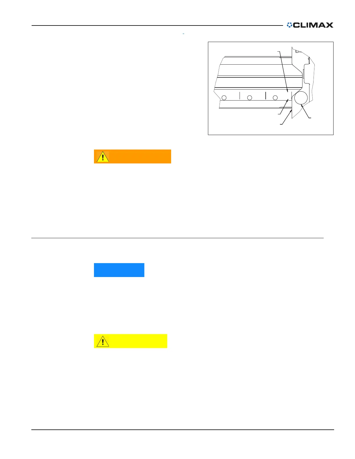
2. Slide the arm to the desired
position.
The machining arm is engraved
with and centimeter markings
on the face of the slide to help
you set the position. Because
the arm is moved radially from
center, the scale shows es and
centimeters in half increments,
measured from the edge of the
main housing (Figure 3-27).
3. Release the safety stop pin.
Position the machining arm so that the safety stop pin engages the
retention notch in the machining arm.
Do not disable the safety stop pin. The safety stop pin is intended to
prevent unwanted shifting of the machining arm, which could result in
serious injury or death.
4. Tighten the clamps to approximately 50 ft-lbs (68 Nm).
3.10 POSITIONING THE COUNTERWEIGHT
The counterweight must be installed when the machine is used in a vertical
machining application. CLIMAX recommends that you always use the
counterweight as it improves the performance of the machine and
produces a flatter surface.
The counterweight arm can be adjusted to balance the machine.
For precise machining and to avoid damage to the machine, the
counterweight and machining arm should always be equally spaced from
the center of the machine.
After positioning the turning arm, do the following to adjust the counterweight to
balance the machine:
1. Suspend the machine from the two lifting points on top of the main body.
FIGURE 3-27. DETAIL OF MACHINING ARM
SPRING
LOADED PIN
MEASUREMENTS
RELATIVE TO THIS EDGE
MACHINING
DIAMETER IN CM
MACHINING DIAMETER
IN INCHES
152
60
142
56
132
52