P/N 80679, Rev. 10 Page 29
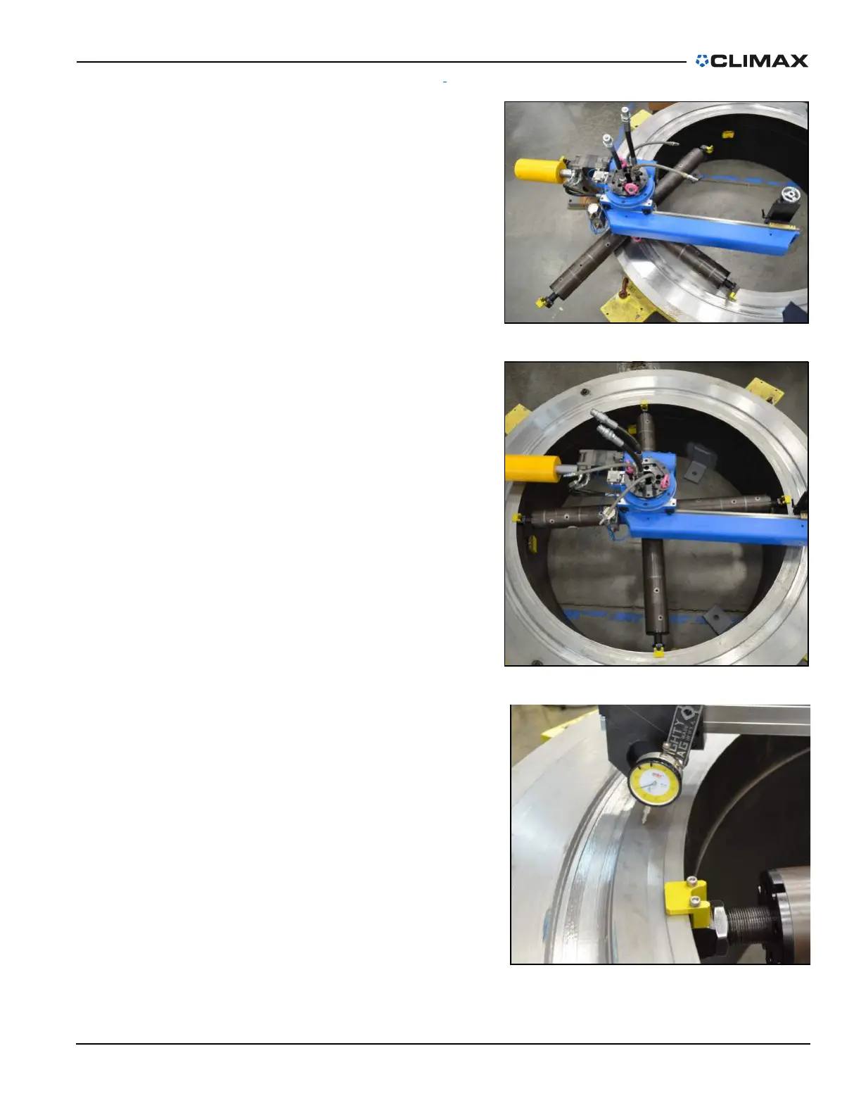
4. Adjust the turning arm and
counterweight arm to the cor-
rect diameter (Figure 3-4). See
Section 3.9 on page 44
and Section 3.10 on page 45
for information on adjusting
the turning and counterweight
arms.
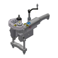
5. Install the machine in the
flange resting on the setup fin-
gers (Figure 3-5).
6. Tighten the jacking feet, and
adjust to level and center the
machine (Figure 3-6). See Sec-
tion 3.6 on page 32 for infor-
mation on centering and
leveling the ID chuck.
FIGURE 3-4. ADJUST THE TURNING ARM
FIGURE 3-5. PLACE THE ID CHUCK IN THE FLANGE
FIGURE 3-6. LEVEL AND CENTER THE ID CHUCK