3.2.1 With the Treadmill and Shock-Detection Controllers
It is recommended to place the controller cabinets on top of each other. In this example, The Treadmill
Controller is placed on the bottom as it is the most heavy. The Shock-Detection Controller is placed in the
middle, adjacent to the Treadmill Controller as it utilizes a short cable for connection of the shock signals.
The Incline Controller is placed on top as it only requires access to the CI-Bus.
Setup all of the controllers as indicated in their respective manuals.
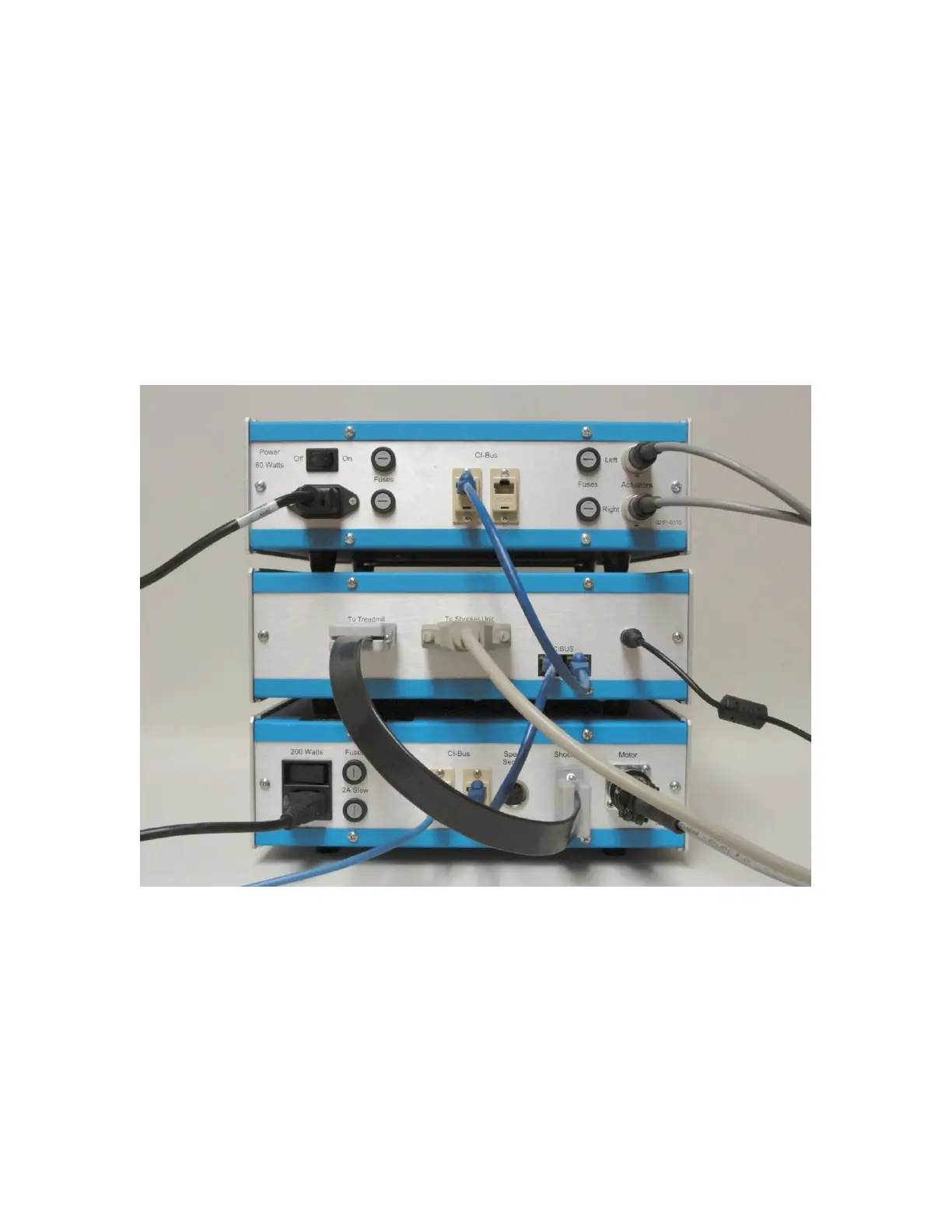
Using the blue CI-Bus data cable, connect the available “CI-Bus” port of the Treadmill Controller to
one of the “CI-Bus” ports on the Shock-Detection Controller.
Using another blue CI-Bus data cable, connect the available “CI-Bus” port of the Shock-Detection
Controller to one of the “CI-Bus” ports on the Incline Controller.
This completes the hardware setup of the Automated Incline Apparatus
 Loading...
