35
0) The upper landing gate is equipped with a similar sill angle as the lower landing gate.
Install the upper landing gate. Ensure that proper running clearances are plumb and
level. Fasten the gate to the tower return wall, using the hardware provided.
Ensure that
the sill angle is properly installed on the gate BEFORE mounting the gate to the
tower wall
. The sill angle has holes for fastening both to the floor and to the running wall.
11
MAKE SURE THAT THE TOP GATE IS MOUNTED
RIGIDLY TO THE SUPPORTS.
111) Proceed to wire the upper landing gate hall and call stations, as per the "ELECTRICAL
CONNECTIONS" section of this manual.
2) Install all provided 3/4" (19 mm) plastic caps into the bolt access holes in the tower side
walls, pla
11
tform gate and upper and lower landing gates. tform gate and upper and lower landing gates.
35
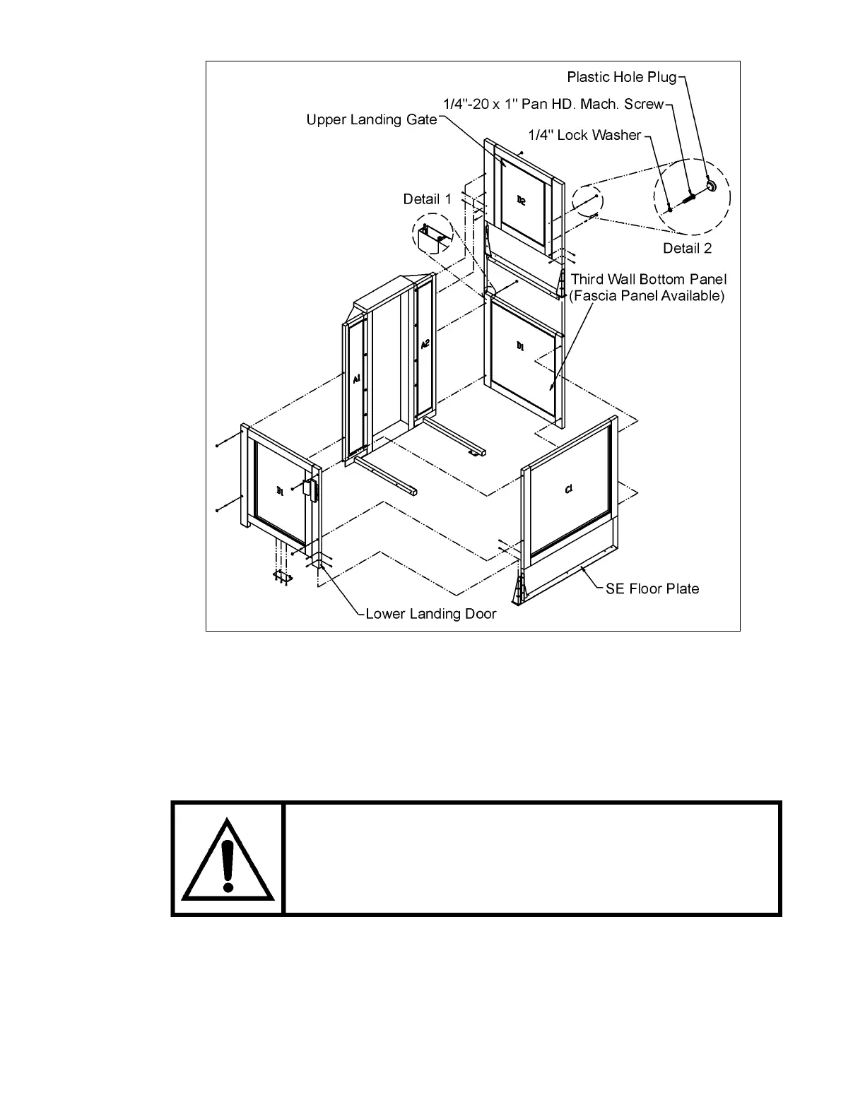
0) The upper landing gate is equipped with a similar sill angle as the lower landing gate.
Install the upper landing gate. Ensure that proper running clearances are plumb and
level. Fasten the gate to the tower return wall, using the hardware provided.
Ensure that
the sill angle is properly installed on the gate BEFORE mounting the gate to the
tower wall
. The sill angle has holes for fastening both to the floor and to the running wall.
MAKE SURE THAT THE TOP GATE IS MOUNTED
RIGIDLY TO THE SUPPORTS.
1) Proceed to wire the upper landing gate hall and call stations, as per the "ELECTRICAL
CONNECTIONS" section of this manual.
2) Install all provided 3/4" (19 mm) plastic caps into the bolt access holes in the tower side
walls, pla
Figure # 21 Semi-Enclosure Drawing - General Arrangement - Non-Pitted Application