Copyright © 2014 congatec AG IGX1m02 123/134
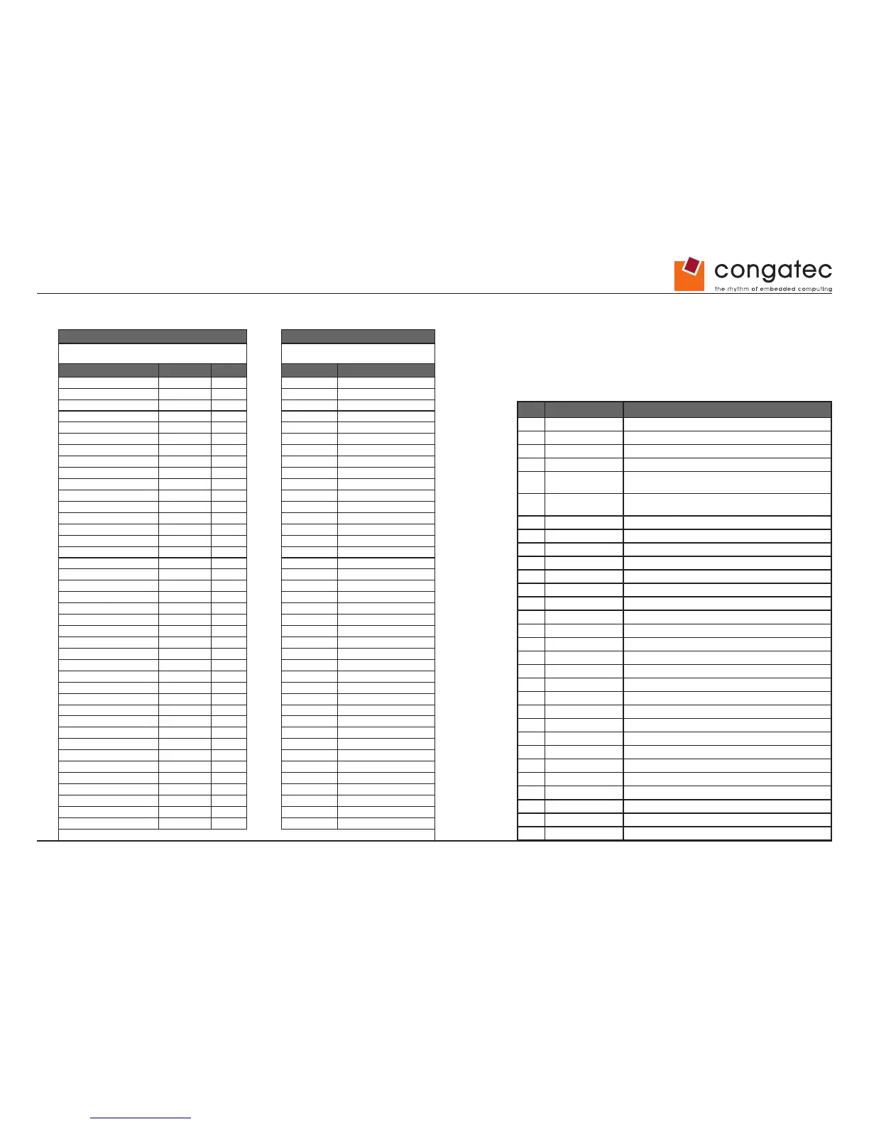
24.4 AUO-M190EG01 V0 LVDS Cable Pinout
conga-IGX AUO-M190EG01 V0
LVDS Connector Hirose DF13-40, straight, SMT JAE FI-XB30SSL-HF15 or compatible
Signal Symbol Pin Pin Symbol
Ground GND 1
Ground GND 2
◄▪▪▪▪▪►
7 GND
LVDS_Out3+ (ODD_3+) LO3+ 3
◄▪▪▪▪▪►
11 RxOIN3+
LVDS_Out7+ (EVEN_3+) LO7+ 4
◄▪▪▪▪▪►
23 RxEIN3+
LVDS_Out3- (ODD_3-) LO3- 5
◄▪▪▪▪▪►
10 RxOIN3-
LVDS_Out7- (EVEN_3-) LO7- 6
◄▪▪▪▪▪►
22 RxEIN3-
Ground GND 7
Ground GND 8
◄▪▪▪▪▪►
14 GND
LVDS_Out2+ (ODD_2+) LO2+ 9
◄▪▪▪▪▪►
6 RxOIN2+
LVDS_Out6+ (EVEN_2+) LO6+ 10
◄▪▪▪▪▪►
19 RxEIN2+
LVDS_Out2- (ODD_2-) LO2- 11
◄▪▪▪▪▪►
5 RxOIN2-
LVDS_Out6- (EVEN_2-) LO6- 12
◄▪▪▪▪▪►
18 RxEIN2-
Ground GND 13
Ground GND 14
◄▪▪▪▪▪►
17 GND
LVDS_Out1+ (ODD_1+) LO1+ 15
◄▪▪▪▪▪►
4 RxOIN1+
LVDS_Out5+ (EVEN_1+) LO5+ 16
◄▪▪▪▪▪►
16 RxEIN1+
LVDS_Out1- (ODD_1-) LO1- 17
◄▪▪▪▪▪►
3 RxOIN1-
LVDS_Out5- (EVEN_1-) LO5- 18
◄▪▪▪▪▪►
15 RxEIN1-
Ground GND 19
Ground GND 20
◄▪▪▪▪▪►
24 GND
LVDS_Out0+ (ODD_0+) LO0+ 21
◄▪▪▪▪▪►
2 RxOIN0+
LVDS_Out4+ (EVEN_0+) LO4+ 22
◄▪▪▪▪▪►
13 RxEIN0+
LVDS_Out0- (ODD_0-) LO0- 23
◄▪▪▪▪▪►
1 RxOIN0-
LVDS_Out4- (EVEN_0-) LO4- 24
◄▪▪▪▪▪►
12 RxEIN0-
Ground GND 25
Ground GND 26
LVDS_CLK1+ (CLK_ODD+) CLK1+ 27
◄▪▪▪▪▪►
9 RxOCLKIN+
LVDS_CLK2+ (CLK_EVEN+) CLK2+ 28
◄▪▪▪▪▪►
21 RxECLKIN+
LVDS_CLK1- (CLK_ODD-) CLK1- 29
◄▪▪▪▪▪►
8 RxOCLKIN-
LVDS_CLK2- (CLK_EVEN-) CLK2- 30
◄▪▪▪▪▪►
20 RxECLKIN-
Ground GND 31
Ground GND 32
DDC-Clock DDCCLK 33
DDC-Data DDCDATA 34
LCD-Power 1) +3.3V / +5V 35
◄▪▪▪▪▪►
28 VCC
LCD-Power 1) +3.3V / +5V 36
◄▪▪▪▪▪►
29 VCC
LCD-Power 1) +3.3V / +5V 37
◄▪▪▪▪▪►
30 VCC
Ground GND 38
Ground GND 39
LCD_PowerOn LCD_On 40
1) selectable via Jumper
Pin Signal Name Description
1 RxO0- Negative LVDS differential data input (Odd data)
2 RxO0+ Positive LVDS differential data input (Odd data)
3 RxO1- Negative LVDS differential data input (Odd data)
4 RxO1+ Positive LVDS differential data input (Odd data)
5 RxO2-
Negative LVDS differential data input (Odd data, H -Sync,V-
Sync,DSPTMG)
6 RxO2+
Positive LVDS differential data input (Odd data, H -Sync,V-
Sync,DSPTMG)
7 GND Power Ground
8 RxOC- Negative LVDS differential clock input (Odd clock)
9 RxOC+ Positive LVDS differential clock input (Odd clock)
10 RxO3- Negative LVDS differential data input (Odd data)
11 RxO3+ Positive LVDS differential data input (Odd data)
12 RxE0- Negative LVDS differential data input (Even clock)
13 RxE0+ Positive LVDS differential data input (Even data )
14 GND Power Ground
15 RxE1- Positive LVDS differential data input (Even data)
16 RxE1+ Negative LVDS differential data input (Even data)
17 GND Power Ground
18 RxE2- Negative LVDS differential data input (Even data)
19 RxE2+ Positive LVDS differential data input (Even data)
20 RxEC- Negative LVDS differential clock input (Even clock)
21 RxEC+ Positive LVDS differential clock input (Even clock)
22 RxE3- Negative LVDS differential data input (Even data)
23 RxE3+ Positive LVDS differential data in put (Even data)
24 GND Power Ground
25 GND Power Ground
26 NC No contact (For AUO test only)
27 GND Power Ground
28 VCC +5.0V Power Supply
29 VCC +5.0V Power Supply
30 VCC +5.0V Power Supply
24.4.1 Panel Pinout AUO-M190EG01 V0