Do you have a question about the Congatec conga-IGX and is the answer not in the manual?
Document's initial release version.
Details of changes made in revision 0.2.
Legal notice and warranty disclaimer.
Specifies the target users of the guide.
Handling precautions for ESD devices.
Explanation of symbols used in the guide.
Copyright information for the document.
Information on product and company trademarks.
Details on the product's limited warranty.
Information on ISO 9001 certification.
Contact and resource information for technical assistance.
Definitions of technical terms used in the manual.
Guidelines for connecting/disconnecting components.
Warning about removing insulating foil from heatsink.
Requirement for memory module insertion into slot A.
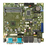
Diagram showing component layout on the board.
Max USB supply current and cable length details.
Notes on memory support and sockets for variants.
Diagram showing proper heatsink placement.
Step-by-step instructions for heatsink assembly.
Warning about removing insulating foil.
Note on using angle SATA cables with heatpipes.
Supported display configurations and combinations.
Usage notes for DisplayPort/LVDS and Windows 8.
Selectable via jumper.
Maximum load per pin.
Jumper for analog or PWM backlight output.
Variable voltage/PWM signal for brightness control.
Polarity can be changed via BIOS Setup.
Custom LVDS settings via LVDS Tool.
Correct mode setting for LVDS panel.
Controls backlight brightness via BIOS or OS.
Sets the backlight brightness level.
Flashing LVDS settings to system BIOS.
PCIe slot type and power considerations.
Details of the DC power input connector.
Warning about simultaneous internal/external power.
Warning about exceeding the overall input power limit.
DC operating range and input current.
Maximum output current per voltage.
Warning about overall input power limit.
Connector compliance with floppy power supply.
8-bit GPIO connector and power provision.
Maximum current per power pin.
Pinout and specifications for internal USB 2.0 ports.
EMI/ESD avoidance with internal USB.
Pinouts for HD Audio and Legacy AC97 connectors.
Note on AC97/Legacy mode pin 7.
SPDIF output connector details.
Details on mSATA and SATA connectors.
Note on mSATA/SATA sharing and DOM power.
Specifications for Mini-PCIe connector.
Pinout for internal COM3 serial port.
Internal serial port is identified as COM3.
Pinout for the internal parallel port.
Specifications of the PCIe x4 extension slot.
Intrusion supervision feature and BIOS setup.
Timestamp for intrusion events.
Fan wiring options and compatibility.
TCV Version and SilentFanConfig.
Pinout for front panel connections.
BIOS recovery and system power-on jumpers.
Potential delay in system power-on.
Fan specifications and processor throttling.
Warning about fan installation/removal.
Warning about fan connector current load.
New settings are permanently stored in BIOS.
Circulating air max 60°C, 24h/7 days usage.
Battery temp range and potential effects.
Typical mains power consumption figures.
Note regarding fanless operation power.
Supported MS Windows OS versions.
Tested Linux distributions with drivers.
List of available software tools for conga-IGX.
OS boot and runtime watchdog supervision.
Optional security chip based on Infineon TPM V1.2.
Accuracy specifications for the onboard RTC.
Steps to reset CMOS settings to defaults.
Note on unofficial Windows XP driver support.
BIOS setting for graphics memory allocation.
Current status of AMD Eyefinity display support.
Current status of HDMI audio transmission.
Issue with low audio recording level on front panel.
Explanation of symbols and text conventions.
Steps to enter the BIOS Setup utility.
How to access the boot menu at startup.
Procedure for booting directly from LAN.
Options for saving or discarding changes.
Displays system configuration details.
Shows board and firmware information.
MAC address of the LAN controller.
CPU designation, ID, and speed.
Memory quantities and frequency.
Specifies the language used in BIOS Setup.
Shows and allows modification of system date/time.
Warning about potential lithium battery discharge.
Shows the current BIOS Setup access level.
Specifies TPM hardware availability.
Specifies if TPM can be used by the OS.
Specifies TPM operation for the next boot.
Shows the current TPM status.
Specifies SATA port operation mode.
Determines mSATA module detection.
Specifies image source for POST.
Using IGD as primary or secondary graphics source.
Configures shared memory for integrated graphics.
Opens submenu to configure LVDS interface.
Determines LVDS interface availability.
Determines LVDS resolution settings.
For LCD panels without DDC support.
Selects the LVDS interface mode.
Swaps LVDS interface channels.
Sets polarity for backlight enabling.
Controls backlight brightness via BIOS or OS.
Sets the backlight brightness level.
Determines POST output mode (graphic/text).
Shows the number of available USB devices.
Specifies legacy USB support availability.
Sets waiting time for USB device detection.
Forces specific device emulation type.
Opens submenu for USB port security settings.
Configures the use of individual USB ports.
Additional options for USB device control.
Shows the system monitoring controller version.
Shows the monitoring controller firmware version.
Displays the current chassis type.
Shows the TCV version.
Specifies automatic fan speed adjustment.
Allows enabling the Azalia HD audio controller.
Enables legacy front audio connector (AC97).
Allows OS to use HPET for time-critical apps.
Specifies LAN 1 controller availability.
Specifies LAN 2 controller availability.
Shows information about the Super IO Chip.
Specifies serial port 0 availability.
Shows I/O address and interrupt for parallel port.
Specifies I/O addresses and interrupts for serial port.
Specifies serial port 1 availability.
Specifies parallel port availability.
Shows I/O address and interrupt for parallel port.
Specifies I/O addresses and interrupts for serial port.
Sets parallel port as input/output or output.
Specifies UEFI network stack availability.
Specifies PXE UEFI Boot via IPv4 support.
Specifies PXE UEFI Boot via IPv6 support.
Describes password allocation scenarios.
Assigns the Administrator password.
Assigns the User password.
Requires user password entry before boot.
Specifies casing monitoring status.
Skips password entry on Wake-on-LAN.
Supplies system BIOS with write protection.
Shows system mode (user or setup).
Indicates if Secure Boot function is active.
Permits booting of unsigned boot loaders.
Specifies Key Management submenu availability.
Submenu for managing boot keys and databases.
Shows the current status of the Platform Key.
Shows the current status of the KEK database.
Shows the current status of the Authorized Signature Database.
Shows the current status of the Forbidden Signature Database.
Requires HDD password entry during boot.
Allows setting/changing HDD passwords.
Shows the current security status of the hard disk.
Indicates if HDD password is supported.
Indicates if HDD password is assigned.
Indicates if the HDD is locked.
Indicates if HDD security status is frozen.
Shows the HDD user password status.
Shows the HDD master password status.
Sets the HDD user password.
Sets the HDD master password.
Manages various power saving functions.
Determines Power LED behavior in standby.
Manages system switch-on sources.
Reduces energy consumption when system is off.
Defines system behavior after power failure.
Reduces energy consumption in hibernate mode.
Enables/disables USB power when system is shut down.
Determines if system can be switched on via LAN.
Specifies system behavior on network signals.
Sets the system switch-on time.
Specifies daily, weekly, or monthly switch-on.
Specifies the day of the month for switch-on.
Specifies system switch-on via USB keyboard.
Specifies whether SMBIOS event log is enabled.
Modifies SMBIOS event log settings.
Specifies whether SMBIOS event log should be deleted.
Specifies action when SMBIOS event log is full.
Specifies if system boots are logged.
Multiple Event Count Increment setting.
Multiple Event Time Window setting.
Enables/disables logging of EFI codes as OEM codes.
Converts EFI status codes to SMBIOS types.
Shows all present SMBIOS event log entries.
Sets NumLock state after system boot.
Shows boot logo instead of POST information.
Reduces boot time for fixed configurations.
Availability of USB devices before OS boot.
Availability of PS/2 devices before OS boot.
Specifies behavior on POST errors.
Removes non-connected boot devices from list.
Specifies support for booting from removable media.
Checks boot sectors for changes.
Prefers USB devices in boot sequence.
Displays and allows modification of boot sequence.
Specifies CSM execution for legacy OS.
Specifies drives allowed for booting.
Specifies PXE option ROM to boot.
Specifies Storage option ROM to boot.
Specifies Video option ROM to boot.
Specifies ROM priority for other PCI devices.
Saves changes and exits BIOS Setup.
Discards changes and exits BIOS Setup.
Saves changes and resets the system.
Discards changes and resets the system.
Options for saving/discarding without exiting.
Selects drive for immediate boot.
Pinout details for AUO G0121SN01 panel.
Cable plan for Green C&C GH093A inverter.
Pinout details for Green C&C GH093A inverter.
Pinout details for AUO G150XG01 panel.
Cable plan for Green C&C GH001A inverter.
Pinout details for Green C&C GH001A inverter.
Pinout details for AUO M170EG01-VD panel.
Cable plan for Green C&C GH053A inverter.
Pinout details for Green C&C GH053A inverter.
Pinout details for AUO-M190EG01 V0 panel.
Cable plan for Green C&C GH001HB inverter.
Pinout details for Green C&C GH001HB inverter.
Pinout details for Sharp LQ190 panel.
Cable plan for PS-DA0412-05 inverter.
Pinout details for PS-DA0412-05 inverter.
Pinout details for Sharp LQ150 panel.
Cable plan for TDK CXA-0349 inverter.
Pinout details for TDK CXA-0349 inverter.
Pinout details for Philips LB121S03-TL01 panel.
Cable plan for Green C&C GH001HB inverter.
Pinout details for Green C&C GH001HB inverter.
Pinout details for NEC NL6448BC33-63D panel.
Cable plan for NEC 104PW201 inverter.
Pinout details for NEC 104PW201 inverter.
Pinout details for Philips LM150X08 panel.
Cable plan for Green C&C GH001A inverter.
Pinout details for Green C&C GH001A inverter.
| Memory | DDR4 |
|---|---|
| SATA | 2x SATA Gen3 |
| M.2 | M.2 2280 |
| USB Ports | USB 3.1, USB 2.0 |
| Networking | 1x Intel® i210 Gigabit Ethernet |
| Ethernet | 1x Intel® i210 Gigabit Ethernet |
| Audio | HD Audio |
| Operating System Support | Windows 10, Linux |
| Operating Temperature | 0°C to 60°C |