Copyright © 2014 congatec AG IGX1m02 47/134
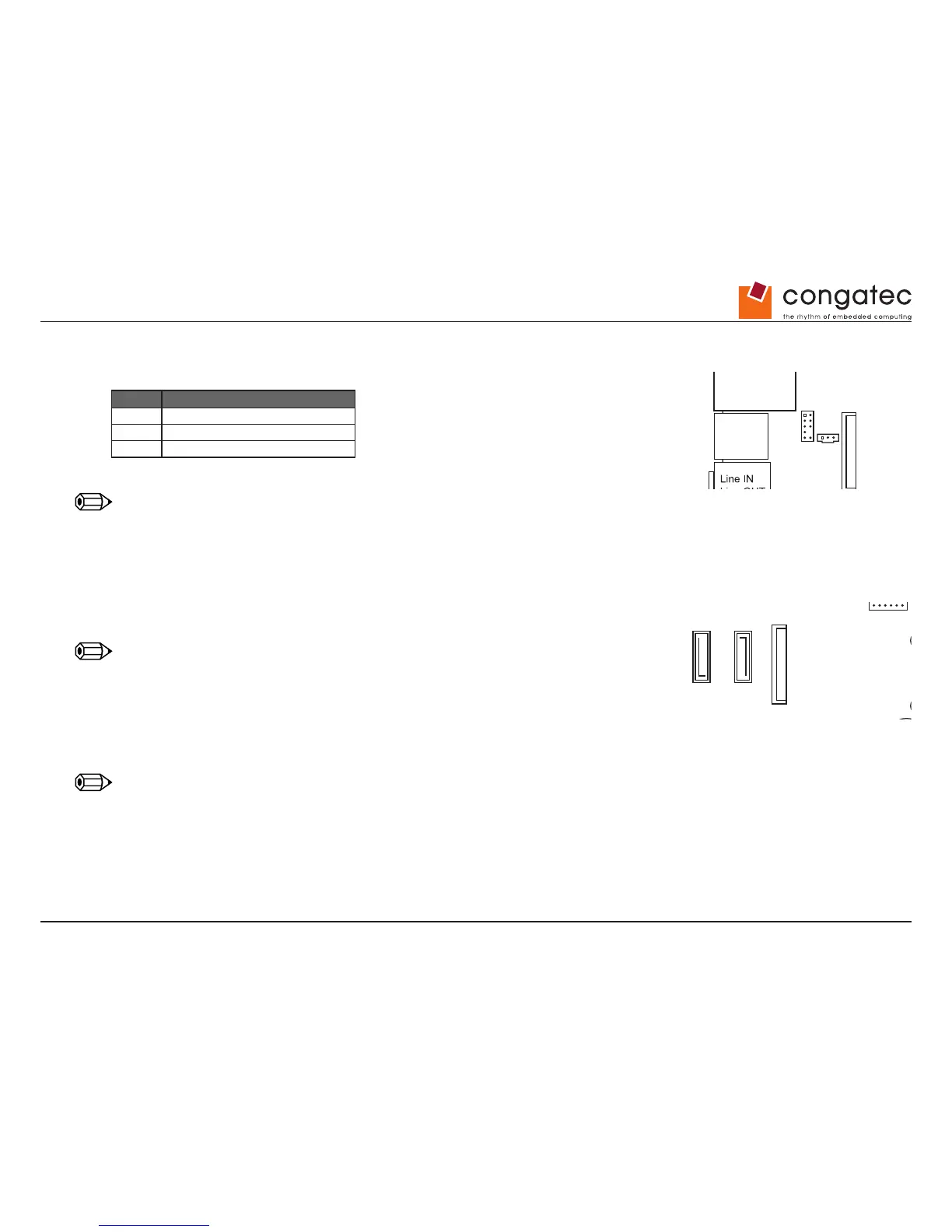
7.5 Internal Audio Ports - SPDIF
Pin Signal
1 VCC
2 SPDIF out
3 GND
Note
Standard connector bracket should directly connect to SPDIFout and GND pins (no signal converter required).
7.6 m-SATA / SATA
Fullsize m-SATA socket
Supports modules with SATA interface.
Note
Mini-PCI-Express or USB is NOT supported by this interface.
Two SATA 3.0 connectors (up to 6Gb/s).
Layout prepared for SATA Disk-On-Module (powered via external power cable only).
Note
SATA-1 and mSATA are shared and can not be used simultaneously.
Drive Power
COM 3
LPT
Front Panel
Power
COM 2
DisplayPort
PCIe X4
FAN 2
1
2
Front Panel 1 = HDD_LED+
2 = Power_LED+
3 = HDD_LED-
4 = Power_LED-
5 = Reset_Switch
DC Plug Jumper Settings1 = + DC
2 = GND
12 V max. 60 Watt
19-24 V max. 100 Watt
Plug: 2.5 / 5.5 / 11 mm
Power 1 = GND
2 = GND
3 = + DC 12 / 19-24 V
4 = + DC 12 / 19-24 V
6 = Power_Switch
7 = Reset_Switch
8 = Power_Switch
9 = Reserved
Drive Power 1 = Vcc 5 V max. 2 A
2 = GND
3 = GND
4 = +12 V max. 2 A
FAN 1
SPDIF
Front Audio
mini PCIe
mSATASATA0 SATA1
LAN
2x USB 2.0
LAN
LVDS
Backlight
TPM GPIO
Buzzer
Battery
2x USB 3.0
2x USB 2.0
LVDS
CPU
Memory Module 1
Memory Module 2
BIOS Recovery Settings
LVDS Supply Settings
USB 2.0
LVDS BL Control Settings
System Power On Settings
1
1
Fan 1 (CPU)
1 = GND
2 = 12 V PWM mode, 4..12 V 3-pin mode
3 = Sense
4 = PWM
1
Fan 2 (Chassis)
4
2
3
2
1
DC DVI-I DisplayPort
COM1 COM2
BIOS Recovery Settings
Normal Operation (default)
Normal Operation (default)
LVDS Supply Settings
LVDS BL Control Settings
System Power On Settings
Always on
BIOS Recovery / Reset to Defaults
VCC 3.3 V
(default)
VCC 5 V
Analog
(default)
PWM
Drive Power
COM 3
LPT
Front Panel
Mouse
Keyboard
Power
COM 2
DisplayPort
PCIe X4
FAN 2
1
2
Front Panel 1 = HDD_LED+
2 = Power_LED+
3 = HDD_LED-
4 = Power_LED-
5 = Reset_Switch
DC Plug Jumper Settings1 = + DC
2 = GND
12 V max. 60 Watt
19-24 V max. 100 Watt
Plug: 2.5 / 5.5 / 11 mm
Power 1 = GND
2 = GND
3 = + DC 12 / 19-24 V
4 = + DC 12 / 19-24 V
6 = Power_Switch
7 = Reset_Switch
8 = Power_Switch
9 = Reserved
Drive Power 1 = Vcc 5 V max. 2 A
2 = GND
3 = GND
4 = +12 V max. 2 A
FAN 1
SPDIF
Front Audio
mini PCIe
LAN
2x USB 2.0
LAN
2x USB 2.0
LVDS
Backlight
TPM GPIO
Buzzer
Battery
2x USB 3.0
LVDS
CPU
Memory Module 1
Memory Module 2
BIOS Recovery Settings
LVDS Supply Settings
USB 2.0
LVDS BL Control Settings
System Power On Settings
1
1
Fan 1 (CPU)
1 = GND
2 = 12 V PWM mode, 4..12 V 3-pin mode
3 = Sense
4 = PWM
1
Fan 2 (Chassis)
4
2
3
2
1
DC DVI-I DisplayPort
COM1 COM2
BIOS Recovery Settings
Normal Operation (default)
Normal Operation (default)
LVDS Supply Settings
LVDS BL Control Settings
System Power On Settings
Always on
BIOS Recovery / Reset to Defaults
VCC 3.3 V
(default)
VCC 5 V
Analog
(default)
PWM