Copyright © 2014 congatec AG IGX1m02 48/134
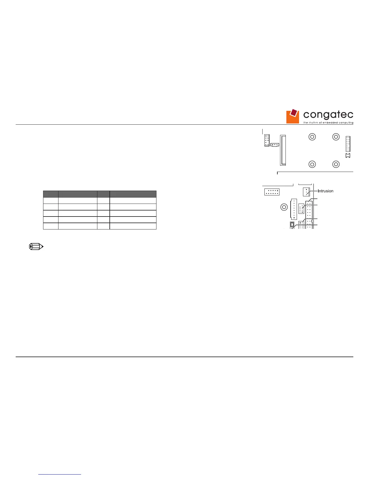
7.7 Mini-PCIe Connector
Mini-PCI Express (Gen2) connector Prepared for halfsize and fullsize modules,
including USB 2.0 interface
7.8 Internal Serial Connector (COM3)
Pin Signal Pin Signal
1 DCD 3 2 DSR 3
3 SIN 3 4 RTS 3
5 SOUT 3 6 CTS 3
7 DTR 3 8 RI 3
9 GND 10 Key
Note
Internal serial port = COM3
Drive Power
COM 3
LPT
Front Panel
Mouse
Keyboard
Power
COM 2
DisplayPort
PCIe X4
FAN 2
1
2
Front Panel 1 = HDD_LED+
2 = Power_LED+
3 = HDD_LED-
4 = Power_LED-
5 = Reset_Switch
DC Plug Jumper Settings1 = + DC
2 = GND
12 V max. 60 Watt
19-24 V max. 100 Watt
Plug: 2.5 / 5.5 / 11 mm
Power 1 = GND
2 = GND
3 = + DC 12 / 19-24 V
4 = + DC 12 / 19-24 V
6 = Power_Switch
7 = Reset_Switch
8 = Power_Switch
9 = Reserved
Drive Power 1 = Vcc 5 V max. 2 A
2 = GND
3 = GND
4 = +12 V max. 2 A
FAN 1
SPDIF
Front Audio
mini PCIe
mSATASATA0 SATA1
LAN
2x USB 2.0
LAN
2x USB 2.0
LVDS
Backlight
GPIO
Buzzer
Battery
2x USB 3.0
2x USB 2.0
LVDS
CPU
Memory Module 1
Memory Module 2
BIOS Recovery Settings
LVDS Supply Settings
USB 2.0
LVDS BL Control Settings
System Power On Settings
1
1
Fan 1 (CPU)
1 = GND
2 = 12 V PWM mode, 4..12 V 3-pin mode
3 = Sense
4 = PWM
1
Fan 2 (Chassis)
4
2
3
2
1
DC DVI-I DisplayPort
COM1 COM2
BIOS Recovery Settings
Normal Operation (default)
Normal Operation (default)
LVDS Supply Settings
LVDS BL Control Settings
System Power On Settings
Always on
BIOS Recovery / Reset to Defaults
VCC 3.3 V
(default)
VCC 5 V
Analog
(default)
PWM
Mouse
Keyboard
Power
COM 2
DisplayPort
PCIe X4
FAN 2
1
2
Front Panel 1 = HDD_LED+
2 = Power_LED+
3 = HDD_LED-
4 = Power_LED-
5 = Reset_Switch
DC Plug Jumper Settings1 = + DC
2 = GND
12 V max. 60 Watt
19-24 V max. 100 Watt
Plug: 2.5 / 5.5 / 11 mm
Power 1 = GND
2 = GND
3 = + DC 12 / 19-24 V
4 = + DC 12 / 19-24 V
6 = Power_Switch
7 = Reset_Switch
8 = Power_Switch
9 = Reserved
Drive Power 1 = Vcc 5 V max. 2 A
2 = GND
3 = GND
4 = +12 V max. 2 A
FAN 1
SPDIF
Front Audio
mini PCIe
mSATASATA0 SATA1
LAN
2x USB 2.0
LAN
2x USB 2.0
TPM GPIO
Buzzer
Battery
2x USB 3.0
2x USB 2.0
LVDS
CPU
Memory Module 1
Memory Module 2
BIOS Recovery Settings
LVDS Supply Settings
USB 2.0
LVDS BL Control Settings
System Power On Settings
1
1
Fan 1 (CPU)
1 = GND
2 = 12 V PWM mode, 4..12 V 3-pin mode
3 = Sense
4 = PWM
1
Fan 2 (Chassis)
4
2
3
2
1
DC DVI-I DisplayPort
COM1 COM2
BIOS Recovery Settings
Normal Operation (default)
Normal Operation (default)
LVDS Supply Settings
LVDS BL Control Settings
System Power On Settings
Always on
BIOS Recovery / Reset to Defaults
VCC 3.3 V
(default)
VCC 5 V
Analog
(default)
PWM