INSTALLATION GUIDELINES
All piping must be installed in
compliance with Part 7, Venting of
Equipment, of the latest edition of the
National Fuel Gas Code NFPA-54/
ANSI 2223.1, local codes or
ordinances and these instructions.
1. Vertical piping is preferred.
2. All horizontal piping must
slope upward from the furnace
a minimum of 1/4" per foot
of run.
3. All horizontal runs must be
supported at least every three
feet. No sags or dips are
permitted.
4. Use only long OR medium
sweep elbows. Use only long
sweep elbows exterior to the
building.
5. All piping between the furnace
and outside wall or roof is 2"
or 3" as specified in Table 17.
A. When using 3" pipe it must
be reduced to 2" before
penetrating the outside wall
or roof.
8. Use a maximum of 18" of 2"
pipe with 3" pipe systems
before penetrating the roof.
C. The 120,000 BTUH
model may require 2-1/2"
components, which come in
the RXGY - D04 Kit.
6. IMPORTANT: DO NOT COM-
MON VENT WITH ANY OTHER
APPLIANCE. DO NOT IN-
STALL PIPING IN THE SAME
CHASE OR CHIMNEY WITH A
METAL OR HIGH TEMPERA-
TURE PLASTIC PIPE FROM
ANOTHER GAS OR FUEL
BURNING APPLIANCE.
7. All vent runs through
unconditioned spaces where
below freezing temperatures are
expected should be insulated
with 1 " thick medium density foil
faced fiber glass, or equivalent
Rubatex/ Armaflex insulation.
8. The minimum vent and
combustion air pipe length is
5 feet.
NOTE: Extend the exhaust a
minimum of 18" vertically above the
cabinet before turning vent.
COMBUSTION AIR PIPE
solvent. See Figure 41, Detail
TERMINATIONS B, for vane location.
Standard vertical terminations If 3 inch pipe is used between the
furnace and outside wall, reduce it
Use two 2" 90° long sweep elbows
to 2 inch before penetrating the wall.
to keep the inlet pointed down
'
1
preventing rain entry. See Figure 40
for proper relationship of com~
bustion air to exhaust termination.
Standard Direct Vent Horizontal
Termination Construction
The standard horizontal intake air
termination for all models is a 2" PVC
coupling with a wind deflector vane
attached.
1. Extend the pipe 1-1/4" through
the wall.
2. Attach a PVC coupling at the
very outside of the wall.
3. Cut a 2-1/4" length of 2" PVC
pipe and connect one end to
another 2" PVC coupling.
4. Connect the other end of this 2"
PVC pipe to the coupling at the
wall. The outer coupling must
terminate 4 inches from the wall.
5. Attach the wind deflector
vane supplied with the
furnace vertically inside the
outer coupling with PVC
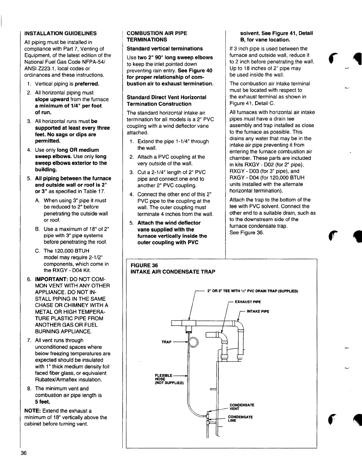
FIGURE36
INTAKE AIR CONDENSATE TRAP
Up to 18 inches of 2" pipe may
be used inside the wall.
The combustion air intake terminal
must be located with respect to
the exhaust terminal as shown in
Figure 41, Detail C.
All furnaces with horizontal air intake
pipes must have a drain tee
assembly and trap installed as close
to the furnace as possible. This
drains any water that may be in the
intake air pipe preventing it from
entering the furnace combustion air
chamber. These parts are included
in kits RXGY • D02 (for 2" pipe),
RXGY - D03 (for 3" pipe), and
RXGY - 004 (for 120,000 BTUH
units installed with the alternate
horizontal termination).
Attach the trap to the bottom of the
tee with PVC solvent. Connect the
other end to a suitable drain, such as
to the downstream side of the
furnace condensate trap.
See Figure 36.
2" OR 3"'TEE WITH 't,• PVC DRAIN TRAP (SUPPLIED)
TRAP
FLEXIBLE
HOSE
(NOT SUPPLIED)
INTAKE PIPE
CONDENSATE
VENT
l-L--+1--- f,i:DENSATE
t
f
36