IMPORTANT: DO NOT CONNECT
IMPORTANT: DO NOT ALLOW
IMPORTANT: WHEN CHANGING TO
THE RIGHT SIDE, INTERCHANGE INTO A COMMON DRAIN LINE
ANY SAGS OR KINKS IN THE
HOSES. Kinks prevent proper
condensate flow. See Figures 50
and 51.
Use a solvent cement that is
compatible with PVC material to
connect the PVC fitting to the trap.
The drain lines may be PVC, nylon
or low density polyethylene.
REVERSING THE TRAP
1. UPFLOW UNITS
The trap may be moved to the right
side for right side drainage. Open the
knockout for the drain on the right
side of the cabinet. Remove the
bracket holding the trap from the left
side. Seal the left side drain hole with
a plug provided in the cloth bag with
the furnace. Position the mounting
bracket and trap so that the drain
elbow is centered in the hole on the
right.
Drill two holes in the cabinet to
mount the bracket. Mount the trap
and bracket to the right side with the
drain elbow pointing through the
knockout. Connect the 1/2" pipe and
tee as noted above. Route the drain
hoses as shown in Figure 52, cut to
the appropriate length, and connect
to the trap with hose clamps
provided.
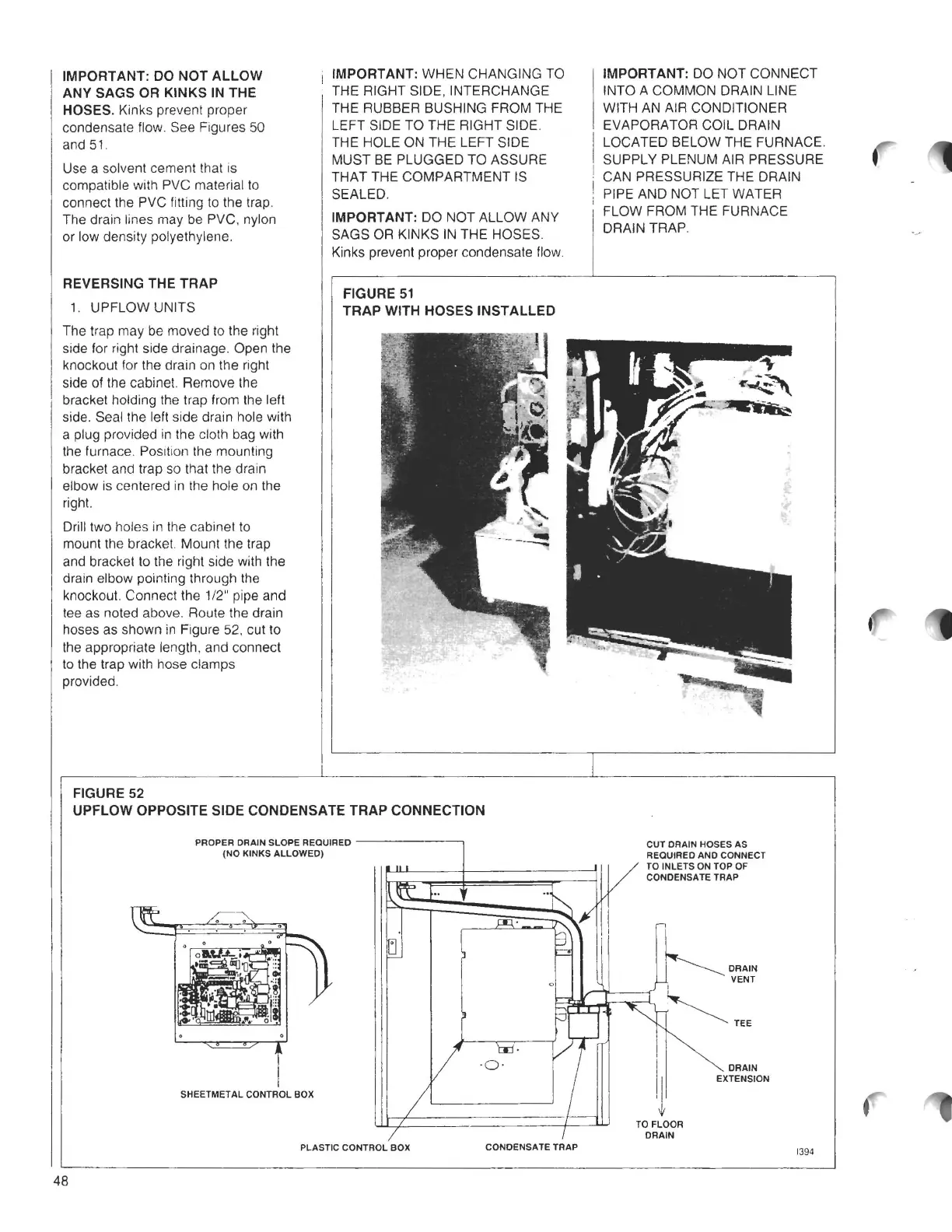
FIGURE 52
THE RUBBER BUSHING FROM THE
LEFT SIDE TO THE RIGHT SIDE.
THE HOLE ON THE LEFT SIDE
MUST BE PLUGGED TO ASSURE
THAT THE COMPARTMENT IS
SEALED.
IMPORTANT: DO NOT ALLOW ANY
SAGS OR KINKS IN THE HOSES.
Kinks prevent proper condensate flow.
FIGURE 51
TRAP WITH HOSES INSTALLED
UPFLOW OPPOSITE SIDE CONDENSATE TRAP CONNECTION
PROPER DRAIN SLOPE REQUIRED -------,
(NO
KINKS ALLOWED)
SHEETMETAL CONTROL BOX
PLASTIC CONTROL BOX
CONDENSATE TRAP
WITH AN AIR CONDITIONER
EVAPORATOR COIL DRAIN
I
LOCATED BELOW THE FURNACE.
SUPPLY PLENUM AIR PRESSURE
I CAN PRESSURIZE THE DRAIN
: PIPE AND NOT LET WATER
1
FLOW FROM THE FURNACE
DRAIN TRAP.
CUT DRAIN HOSES AS
REQUIRED AND CONNECT
TO INLETS ON TOP OF
CONDENSATE TRAP
11
'¥
TO FLOOR
DRAIN
DRAIN
VENT
DRAIN
EXTENSION
1394
48