company for the location of the
manual main shut-off valve. The gas
line and manual gas valve must be
adequate in size to prevent undue
pressure drop and never smaller
than the pipe size to the combination
gas valve on the furnace. Refer to
Table 19 for the recommended gas
pipe size.
See Figure 59 for typical gas pipe
connections. A ground joint union
must be installed within three feet of
the furnace so the control assembly
may be easily removed. Install a
manual shut-off valve upstream of
this ground joint union. The valve
should be readily accessible for
turning the gas supply on or off. A
drip leg should be installed in the gas
supply line as close to the furnace as
possible.
A pipe compound resistant
to the action of liquefied petroleum
gases must be used on all threaded
connections.
IMPORTANT: WHEN MAKING GAS
PIPE CONNECTIONS, USE A
BACK-UP WRENCH TO PREVENT
ANY TWISTING OF THE CONTROL
ASSEMBLY AND GAS VALVE. ANY
STRAINS ON THE GAS VALVE
CAN CHANGE THE POSITION OF
THE GAS ORIFICES IN THE
BURNERS. THIS CAN CAUSE
ERRATIC FURNACE OPERATION.
IMPORTANT: ENSURE THAT THE
FURNACE GAS CONTROL VALVE
NOT BE SUBJECTED TO HIGH
GAS LINE SUPPLY PRESSURES.
DISCONNECT THE FURNACE AND
ITS INDIVIDUAL SHUT-OFF VALVE
FROM THE GAS SUPPLY PIPING
DURING ANY PRESSURE
TESTING THAT EXCEEDS 1/2
P.S.I.G. (3.48
KPA). The furnace
must be isolated from the gas supply
piping by closing its individual
manual shut-off valve during any
pressure testing of the gas supply
piping system at test pressures equal
or less than 1/2 p.s.i.g. (3.48 kPa).
IMPORTANT: DO NOT RUN A
FLEXIBLE GAS CONNECTOR
INSIDE THE UNIT. EXTEND THE
1/2" BLACK PIPE FROM THE GAS
VALVE TO THE OUTSIDE OF THE
CABINtT. IF ALLOWED BY CODE,
CONNECT ANY FLEXIBLE GAS
CONNECTOR FROM THERETO
THE GAS PIPING. The gas pipe
gasket in the cabinet does not seal
around a flexible gas connector. It is
important to have all openings in the
cabinet burner compartment sealed
for proper furnace operation.
GAS PRESSURE
Natural gas supply pressure should
be 5" to 10.5" w.c. LP gas supply
pressure should be 11" to 13" w.c.
This pressure must be maintained
with all other gas fired appliances in
operation. The minimum supply
pressure to the gas valve for proper
furnace input adjustments is 5" w.c.
for natural gas, however 6" - 7" is
recommended. The minimum supply
pressure is 11" w.c. for LP gas.
A WARNING: NEVER PURGE
A GAS LINE INTO THE COMBUS-
TION CHAMBER. NEVER USE
MATCHES, FLAME OR ANY
IGNITION SOURCE FOR
CHECKING LEAKAGE. DOING
SO MAY RESULT IN FIRE,
EXPLOSION, PERSONAL INJURY
OR DEATH. To check for gas
leakage use an approved chloride-
free soap and water solution, an
electronic combustible gas detector
(see Figure 60), or other approved
method.
FIGURE 60
ELECTRONIC COMBUSTIBLE
GAS DETECTOR
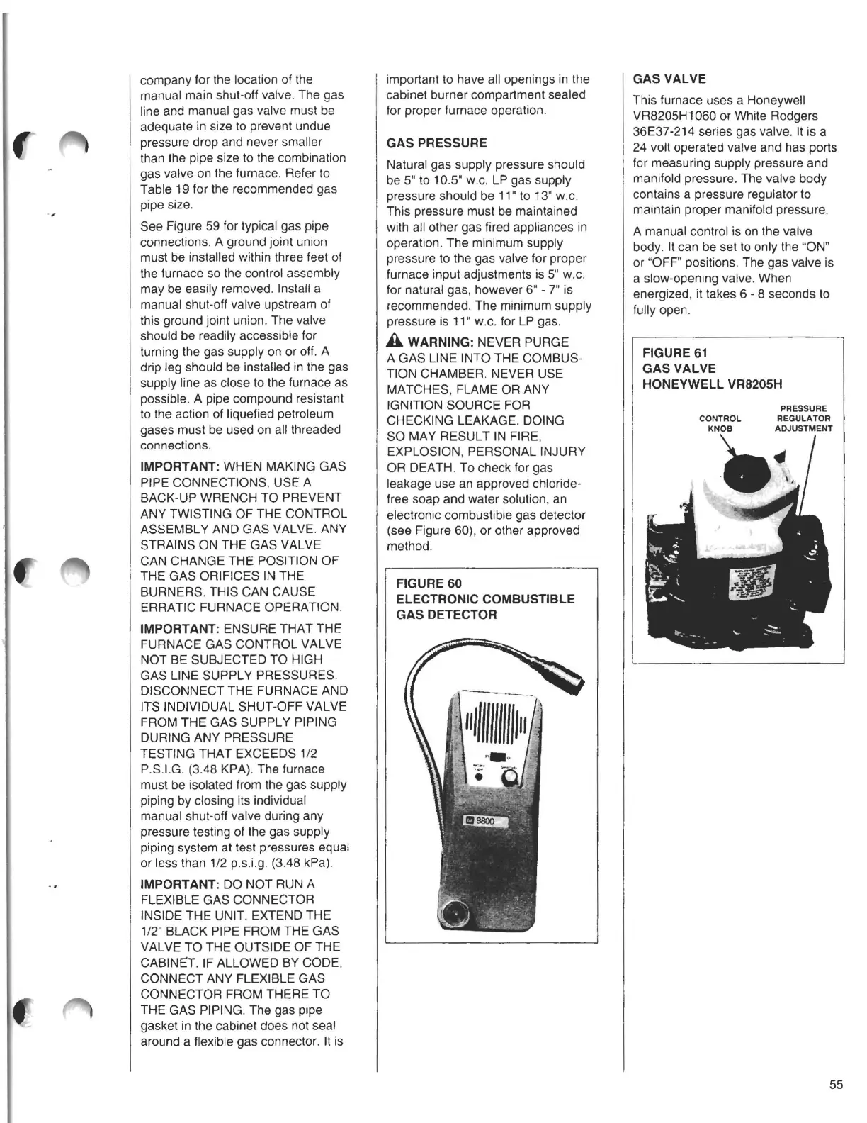
GAS VALVE
This furnace uses a Honeywell
VR8205H1060 or White Rodgers
36E37-214 series gas valve. It is a
24 volt operated valve and has ports
for measuring supply pressure and
manifold pressure. The valve body
contains a pressure regulator to
maintain proper manifold pressure.
A manual control is on the valve
body. It can be set to only the "ON"
or "OFF" positions. The gas valve is
a slow-opening valve. When
energized, it takes 6 - 8 seconds to
fully open.
FIGURE 61
GAS VALVE
HONEYWELL VR8205H
PRESSURE
CONTROL REGULATOR
KNOB ADJUSTMENT
•
55