LP CONVERSION
The valve can be converted to use
liquified petroleum (LP) gas by
replacing the pressure regulator
spring with the conversion kit spring.
This LP kit spring allows the
regulator to maintain the proper
manifold pressure for LP gas. The
correct burner LP orifices are also
included in the kit.
NOTE:Order the correct LP
conversion kit from the furnace
manufacturer.
Furnace conversion
to LP gas must be performed by a
qualified technician.
The furnace
LP kits are listed below.
TABLE20
LP KITS
FUELCOOE KITNO.
LOCATION
DC/OF EP80H
us.,0- 7999
DC/OF
FP-02
EP88H U.S , 8000' and Above
FP-03
DC /OF
EP81H
Canada.0 - 4500'
FP-05
EB/EC/EH IEJ
EBIEC/EH/EJ
FP-02
FP-03
U.S., 0 - 7999'
U.S., 8000' and Above
EB / EC/ EH / EJ
FP-05
Canada.O - 4500'
EK/EL
EK/EL
FP-02
FP-03
U.S.. 0 7999'
U.S., 8000' and Above
EK/ EL FP-05
Canada,O - 4500'
To change orifice spuds for either
conversion to LP or for elevation,
shut off the manual main gas valve
and remove the gas manifold.
Replace the orifice spuds and
reassemble in reverse order. Consult
Table 21 if there is any question
concerning orifice sizing.
TABLE21
ORIFICE SIZES
U.S.
0 - 8000 FT. 8001 FT. & ABOVE
Nat'I Gas #50 #51
LP Gas
115mm 1.10 mm
CANADIAN 0-2000 FT. 2001• 4500 FT.
Nat'IGas #50 #50
LP Gas 1.15mm
U5mm
,
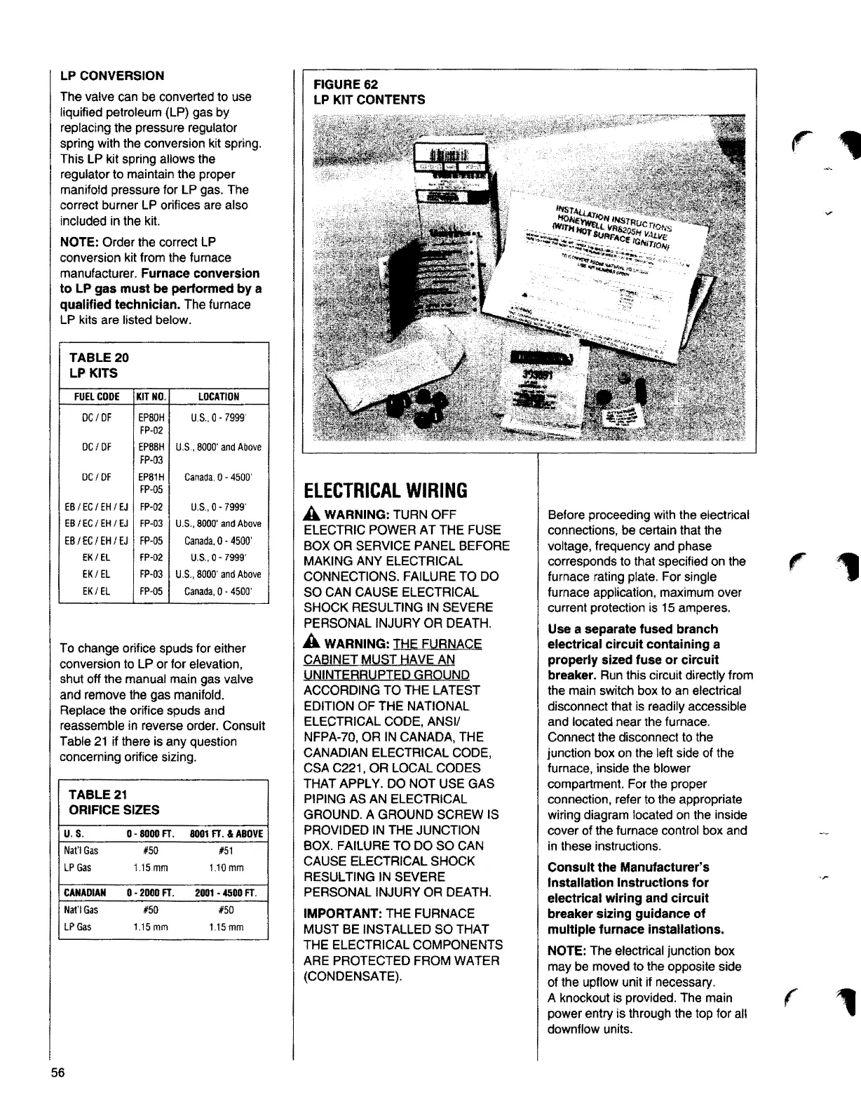
FIGURE62
LP KIT CONTENTS
ELECTRICALWIRING
A WARNING:TURN OFF
ELECTRIC POWER AT THE FUSE
BOX OR SERVICE PANEL BEFORE
MAKING ANY ELECTRICAL
CONNECTIONS. FAILURE TO DO
SO CAN CAUSE ELECTRICAL
SHOCK RESULTING IN SEVERE
PERSONAL INJURY OR DEA TH.
A WARNING:THE FURNACE
QA8!NET MUST t!AVE AN
!,JNINTERRUPTEIJ GRQUND
ACCORDING TO THE LATEST
EDITION OF THE NATIONAL
ELECTRICAL CODE,
ANSI/
NFPA-70, OR IN CANADA, THE
CANADIANELECTRICAL CODE,
CSA C221, OR LOCAL CODES
THAT APPLY. DO NOT USE GAS
PIPING
AS AN ELECTRICAL
GROUND. A GROUND SCREW IS
PROVIDED IN THE JUNCTION
BOX. FAILURE TO DO SO CAN
CAUSE ELECTRICAL SHOCK
RESULTING IN SEVERE
PERSONAL INJURY OR DEATH.
IMPORTANT:THE FURNACE
MUST BE INSTALLED SO THAT
THE ELECTRICAL COMPONENTS
ARE PROTECTED FROM WATER
(CONDENSATE).
Before proceeding with the electrical
connections, be certain that the
voltage, frequency and phase
corresponds to that specified on the
furnace rating plate. For single
furnace application, maximum over
current protection is 15 amperes.
Use a separate fused branch
electrical circuit containing a
properly sized fuse or circuit
breaker.
Run this circuit directly from
the main switch box to an electrical
disconnect that is readily accessible
and located near the furnace.
Connect the disconnect to the
junction box on the left side of the
furnace, inside the blower
compartment. For the proper
connection, refer to the appropriate
wiring diagram located on the inside
cover of the furnace control box and
in these instructions.
Consult the Manufacturer's
Installation Instructions for
electrical wiring and circuit
breaker sizing guidance of
multiple furnace installations.
NOTE:
The electrical junction box
may be moved to the opposite side
of the upflow unit if necessary.
A knockout is provided. The main
power entry is through the top for all
downflow units.
r
r
r
,
56