BURNER SUPPORT MOUNTED OVER
TEMPERATURE SWITCH
TEMPERATURE SETTING
ALL SIZES: 300°
Cannot be reset until temperature
cools to 240°
SWITCHNUMBER FURNACEMODELS
ONE SWITCH 04, 06
TWO SWITCHES 07, 09, 10
TWO SWITCHES (-)GTA/(-)GSA- 12
THREESWITCHES (-)GRA-12
Over temperature switches protect
against over heating conditions in
the furnace vestibule. If an over
temperature switch opens, check for:
1. A lack of combustion air,
2. A blocked heat exchanger,
3. A damaged heat exchanger.
If an over temperature switch opens
ALWAYScheck for a proper supply
of combustion air.
Operation.When enough heat backs
out into the furnace vestibule, its
contacts open. This switch
communicates with the integrated
furnace control board to stop the
burners. The switch contacts must be
manually reset by pressing the red
button on the control.
If a switch opens, the induced draft
blower (IDB) and main furnace
blower operate continuously until the
switch resets. Once the switch resets
the IDB stops and the main blower
continues to run for its set off delay
timing.
Check.The following voltage test can
be used.
1. Turn power on to the furnace.
2. Use a voltmeter to check for 24
vac across the switch contacts.
3. A 24 vac reading indicates an
open switch.
4.
A zero (0) vac reading indicates
a closed switch.
Replace the switch if pressing the
button does not reset it.
TRANSFORMER
The system transformer requires
115 volt input to the primary winding.
The secondary winding is rated at a
nominal 24 volts, 40 VA output. The
secondary voltage depends upon the
incoming primary voltage.
The furnace electronic ignition
system requires that one side of the
control transformer low voltage
circuit be grounded to the furnace
case. This enables the ignition
control to recognize burner
operation.
If the thermostat low voltage wires
are connected to the furnace
terminal board and primary power is
applied to the unit, at least one wire
can be powered with 24 volts, even
with the thermostat in the "OFF
position.
IMPORTANT:TOUCHING ANY
METAL SURFACE OF THE
FURNACE OR CONDENSING UNIT
WITH A BARE CONTROL WIRE
MAY DAMAGE THE TRANS-
FORMER SECONDARY WINDING
OR INTEGRATED FURNACE
CONTROL BOARD.
Some transformers now come with a
replaceable fuse in one of the
secondary leads. This fuse is a 2.0
amp, slow blow fuse. It protects low
voltage components from any shorts
to ground or other high amperage
conditions. The fuse can be ordered
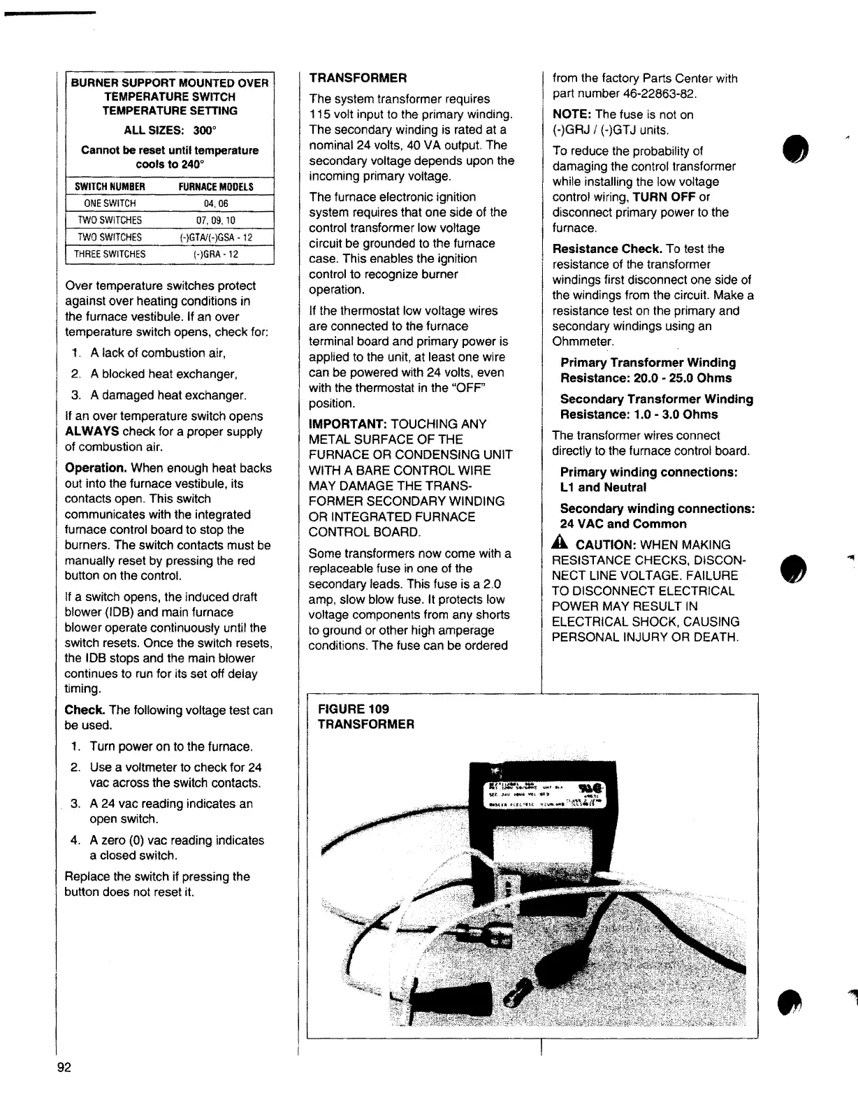
FIGURE 109
TRANSFORMER
from the factory Parts Center with
part number 46-22863-82.
NOTE:The fuse is not on
(-)GRJ / {-)GTJ units.
To reduce the probability of
damaging the control transformer
while installing the low voltage
•
control wiring, TURN OFF or
disconnect primary power to the
furnace.
Resistance Check. To test the
resistance of the transformer
windings first disconnect one side of
the windings from the circuit. Make a
resistance test on the primary and
secondary windings using an
Ohmmeter.
Primary Transformer Winding
Resistance:
20.0 - 25.0 Ohms
Secondary Transformer Winding
Resistance:
1.0 - 3.0 Ohms
The transformer wires connect
directly to the furnace control board.
Primary winding connections:
L 1 and Neutral
Secondary winding connections:
24 VAC and Common
A CAUTION:WHEN MAKING
RESISTANCE CHECKS, DISCON-
NECT LINE VOLTAGE. FAILURE
TO DISCONNECT ELECTRICAL
•
POWER MAY RESULT IN
ELECTRICAL SHOCK, CAUSING
PERSONAL INJURY OR DEATH.
92