,1f
••
1
·/
I'
: I
:
1
:
I I
I I
- :::: , :
GAS SUPPLY
WARNING: THIS FURNACE IS
EQUIPPED AT THE FACTORY FOR
USE ON NATURAL GAS ONLY.
CONVERSION TO LP GAS
REQUIRES A SPECIAL KIT
SUPPLIED BY THE DISTRIBUTOR
OR MANUFACTURER. MAILING
ADDRESSES ARE LISTED ON THE
FURNACE RATING PLATE, PARTS
LIST AND WARRANTY. FAILURE
TO USE THE PROPER CONVER-
SION KIT CAN CAUSE FIRE,
CARBON MONOXIDE POISONING,
EXPLOSION, PROPERTY
DAMAGE, PERSONAL INJURY OR
DEATH. See the conversion kit index
supplied with the furnace. This index
identifies the proper LP Gas
Conversion Kit required for each
particular furnace.
IMPORTANT: ANY ADDITIONS,
CHANGES OR CONVERSIONS
REQUIRED FOR THE FURNACE
TO SATISFACTORILY MEET THE
APPLICATION SHOULD BE MADE
BY A QUALIFIED INSTALLER,
SERVICE AGENCY OR THE GAS
SUPPLIER, USING FACTORY
SPECIFIED OR APPROVED
PARTS.
Below 8000' elevation, do not make
any attempt to derate the furnace by
changing gas orifices or the gas
pressure. Allow the natural derate of
the gas to occur. The natural derate
is approximately 1 .8% per 1000 feet.
Below 8000' elevation, no orifice
sizing or other derate procedures are
necessary unless the natural gas
BTU content exceeds 1075 BTUfft3
at sea level or the LP gas BTU
content exceeds 2500 BTU/ft3 at sea
level. If the heating values exceed
these levels, consult the
manufacturer for specific derate
procedures.
GAS PIPING
Gas piping should be installed in
accordance with all local codes and
regulations of the utility company.
IMPORTANT: CONNECT THE
FURNACE ONLY TO GAS
SUPPLIED BY A COMMERCIAL
UTILITY.
If possible, the gas supply line
should be a separate line running
directly from the meter to the
furnace. Consult the local gas
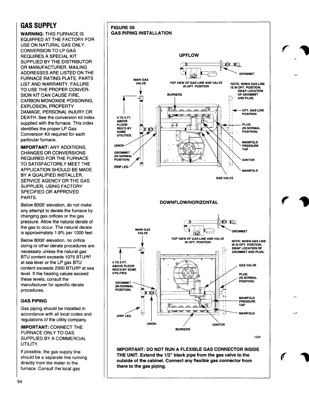
FIGURE59
GAS PIPING INSTALLATION
UPFLOW
MAIN GAS
VALVE
TOP VIEW OF GAS LINE AND VALVE
NOTE: WHEN GAS LINE
IN OPT. POSITION
IS IN OPT. POSITION,
SWAP LOCATION
OFGROMMET
AND PLUG.
~OPT.GAS LINE
POSITION
4T05FT.
ABOVE
FLOOR
~n
◄
lll(~]--i\,_...-
PLUG
REQ'DBY
(IN NORMAL
SOME
POSITION)
UTILITIES.
MANIFOLD
UNION
PRESSURE
TAP
GROMMET
(IN NORMAL
POSITION)-
IGNITOR
DRIP LEG/
MANIFOLD
DOWN FLOW/HORIZONTAL
GAS VALVE
MAIN GAS
VALVE
TOP VIEW OF GAS LINE AND VALVE
IN OPT. POSITION
NOTE: WHEN GAS LINE
+
IS IN OPT. POSITION,
SWAPLOCATION OF
t
I
I
:
I
I
I
GROMMET AND PLUG.
4 TOSFT.
ABOVE FLOOR
REO'D BY SOME
UTILITIES.
I
I
i
I
I
GAS VALVE
PLUG
I I
: : / (IN NORMAL
GROMMET
~
POSITION)
(IN NORMAL
POSITION)
=::':
MANIFOLD
UNION
IGNITOR
BURNERS
1328
IMPORTANT: DO NOT RUN A FLEXIBLE GAS CONNECTOR INSIDE
THE UNIT. Extend the 1/2" black pipe from the gas valve to the
outside of the cabinet. Connect any flexible gas connector from
there to the gas piping.
54