INSTALLATION GUIDELINES
All exhaust vent piping must be
installed in compliance with Part 7,
Venting of Equipment, of the latest
edition of the National Fuel Gas
Code NFPA 54/ANSI A223.1, or
CAN/CGA-B149.1 and .2, local
codes or ordinances and these
"
instructions.
1. Vertical piping is preferred.
2.
All horizontal piping must
slope
upward a minimum of 1/4"
per foot
of run.
3.
Support all horizontal runs at
least
every three feet. No sags
or dips are permitted.
4. Use medium or long radius
sweep elbows.
5.
All piping between the furnace
and outside wall or roof is 2"
or 3"
as specified in Table 16.
A. When using 3" pipe it must
be reduced to 2" before
penetrating the outside wall
or roof.
B. Use a maximum of 18" of 2"
pipe with 3" pipe systems
before penetrating the wall
or roof.
~
6. IMPORTANT:DO NOT
COMMON VENT WITH ANY
OTHER APPLIANCE. DO NOT
INSTALL PIPING IN THE SAME
CHASE OR CHIMNEY WITH
A
METAL OR HIGH TEMPERA-
TURE PLASTIC PIPE FROM
ANOTHER GAS OR FUEL
BURNING APPLIANCE.
7. All vent runs through uncon-
ditioned spaces where below
freezing temperatures are
expected should be insulated
with 1" thick medium density foil
faced fiber glass, or equivalent
Rubatexl Armaflex insulation.
8. The minimum pipe length is
5 feet.
Size the exhaust pipe as specified in
Table 17. This table lists the
maximum allowable length in feet of
the exhaust pipe that may be used
(shaded area) for all furnace inputs
as related to the number of elbows
required and the termination.
NOTE:Extend the exhaust a
minimum of 18" vertically above the
cabinet before turning the vent.
""
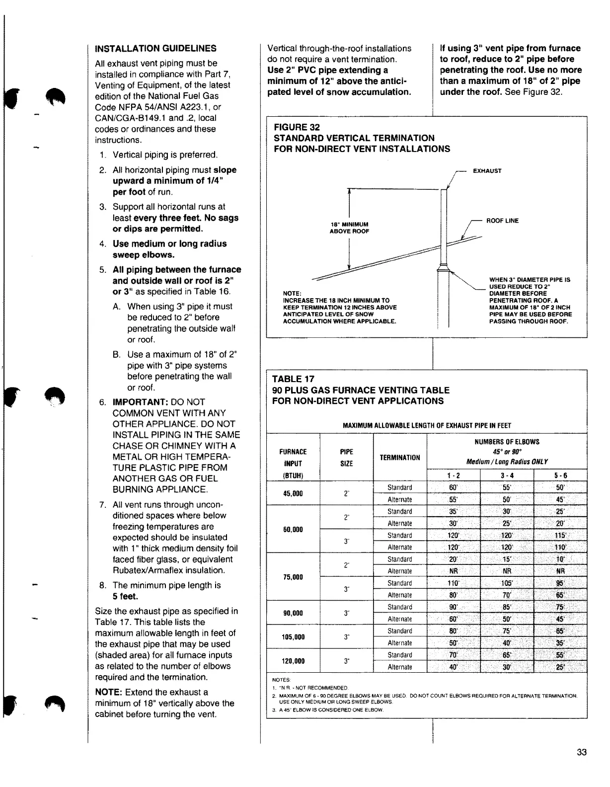
Vertical through-the-roof installations
do not require a vent termination.
Use 2" PVC pipe extending a
minimum of 12" above the antici-
pated level of snow accumulation.
If using 3" vent pipe from furnace
to roof, reduce to 2" pipe before
penetrating the roof. Use no more
than a maximum of 18" of 2" pipe
under the roof.
See Figure 32.
FIGURE32
STANDARDVERTICAL TERMINATION
FOR NON-DIRECT VENT INSTALLATIONS
r
EXHAUST
18" MINIMUM
ABOVE ROOF
~=
~
ROOFLINE
===
~
WHEN 3" DIAMETER PIPE IS
I
~
USED REDUCE TO 2"
NOTE:
INCREASE THE 18 INCH MINIMUM TO
KEEP TERMINATION 12 INCHES ABOVE
ANTICIPATEO LEVEL OF SNOW
ACCUMULATION WHERE APPLICABLE.
TABLE 17
90 PLUS GAS FURNACE VENTING TABLE
FOR NON-DIRECT VENT APPLICATIONS
DIAMETER BEFORE
PENETRATING ROOF.
A
MAXIMUM OF 18" OF 2 INCH
PIPE MAY BE USED BEFORE
PASSING THROUGH ROOF.
MAXIMUMALLOWABLELENGTHOF EXHAUST PIPE IN FEET
FURNACE
INPUT
{BTUH)
45,000
60,000
75,000
90,000
105,000
120,000
NOTES·
PIPE
SIZE
2·
2'
3·
2"
3"
3"
3"
3"
1. ·N R. - NOT RECOMMENDED
TERMINATION
1 - 2
Standard 60'
Alternate
55'
Standard
35'
Alternate
30'
Standard
120'
Alternate 120'
Standard 20'
Alternate NR
Standard
110'
Alternate
80'
Standard 90'
Alternate
60'
Standard 80'
Alternate
50'
Standard
70'
Alternate
40'
NUMBERSOF ELBOWS
45• orgo•
MediumI LongRadiusONLY
3-4
5-6
55·
50'
50' 45'
30'
25'
25'. 20'
120'
...
115'•
120'
!l<Y
15'
iir
!'JR .VR
105'
95'.·
'.
iii
.·,.
70' ..
..
, .. '
85'
75:
'
◄
S'
50'
.
75' '
.• ..·115'·.
.
~-40'
..
'
•
s&f'
65'.
..
30'
··.•~
,,
2. MAXlMUM OF 6 • 90 DEGREE ELBOWS MAY BE USED. DO NOT COUNT ELBOWS REQUIRED FOR ALTERNATE TERMINATION.
USE ONLY MEDIUM OR LONG SWEEP ELBOWS.
3. A 45" RBOW IS CONSIDERED ONE ELBOW.
I
33