ISOLATIONRELAY
IMPORTANT: Not all electronic night
setback thermostats are compatible
with the furnace control system.
Some may require an isolation relay.
If an isolation relay is needed, install
it as close to the control board as
possible. Use a single-pole, single-
throw relay with a 24-volt operating
coil. The relay contacts should be
designed for 24-volt loads.
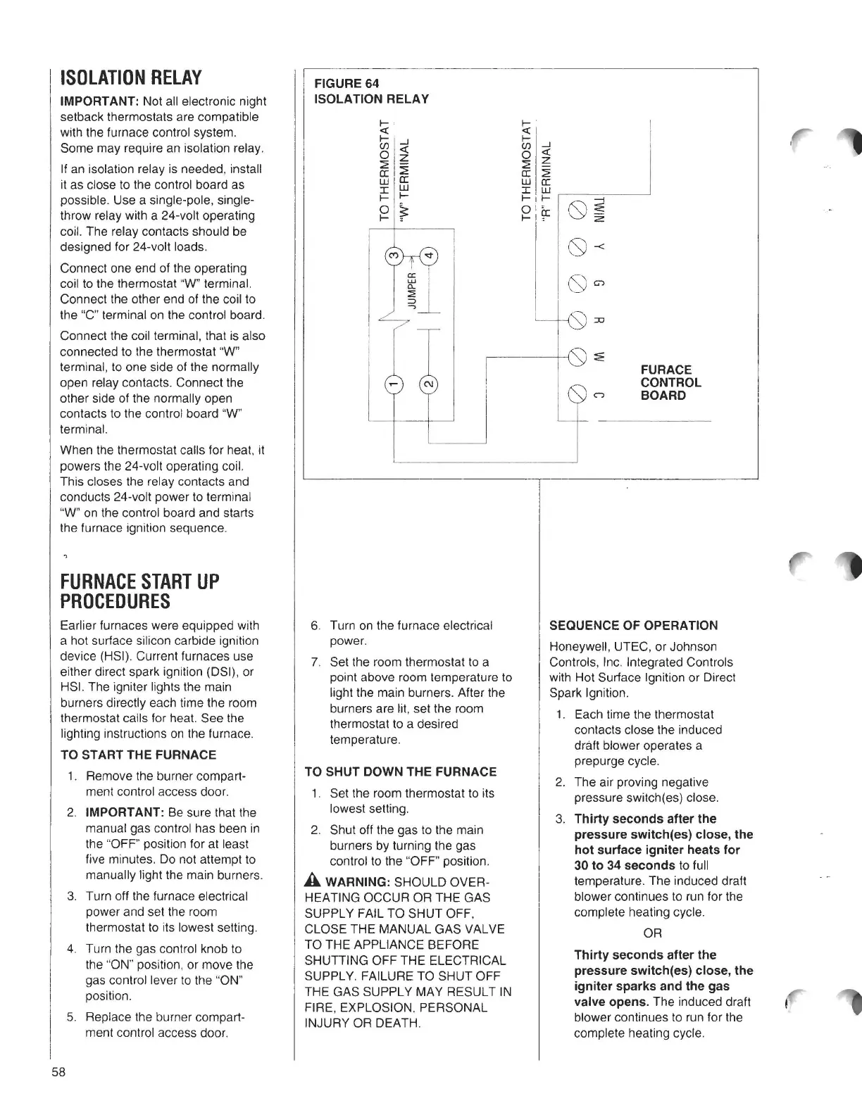
Connect one end of the operating
coil to the thermostat "W' terminal.
Connect the other end of the coil to
the "C" terminal on the control board.
Connect the coil terminal, that is also
connected to the thermostat "W"
terminal, to one side of the normally
open relay contacts. Connect the
other side of the normally open
contacts to the control board "W'
terminal.
When the thermostat calls for heat, it
powers the 24-volt operating coil.
This closes the relay contacts and
conducts 24-volt power to terminal
"W" on the control board and starts
the furnace ignition sequence.
FURNACE UPSTART
PROCEDURES
Earlier furnaces were equipped with
a hot surface silicon carbide ignition
device (HSI). Current furnaces use
either direct spark ignition (OSI), or
HSI. The igniter lights the main
burners directly each time the room
thermostat calls for heat. See the
lighting instructions on the furnace.
TO START THE FURNACE
1. Remove the burner compart-
ment control access door.
2.
IMPORTANT: Be sure that the
manual gas control has been in
the "OFF" position for at least
five minutes. Do not attempt to
manually light the main burners.
3. Turn off the furnace electrical
power and set the room
thermostat to its lowest setting.
4. Turn the gas control knob to
the "ON" position, or
move the
gas control lever to the "ON"
position.
5. Replace the burner compart-
ment control access door.
FIGURE 64
ISOLATION RELAY
a:
u.J
0..
:::E
~
--,
C\J
6. Turn on the furnace electrical
power.
7. Set the room thermostat to a
point
above room temperature to
light the main burners. After the
burners are lit, set the room
thermostat to a desired
temperature.
TOSHUTDOWNTHEFURNACE
1. Set the room thermostat to its
lowest setting.
2. Shut off the gas to the main
burners by turning the gas
control to the "OFF" position.
A WARNING: SHOULD OVER-
HEATING OCCUR OR THE GAS
SUPPLY FAIL TO SHUT OFF,
CLOSE THE MANUAL GAS VALVE
TO THE APPLIANCE BEFORE
SHUTTING OFF THE ELECTRICAL
SUPPLY. FAILURE TO SHUT OFF
THE GAS SUPPLY MAY RESULT IN
FIRE, EXPLOSION, PERSONAL
INJURY OR DEATH.
FURACE
CONTROL
BOARD
SEQUENCE OF OPERATION
Honeywell, UTEC, or Johnson
Controls, Inc. Integrated Controls
with Hot Surface Ignition or Direct
Spark Ignition.
1. Each time the thermostat
contacts close the induced
draft blower operates a
prepurge cycle.
2. The air proving negative
pressure switch(es) close.
3.
Thirty seconds after the
pressure switch(es) close, the
hot surface igniter heats for
30 to 34 seconds
to full
temperature. The induced draft
blower continues to run for the
complete heating cycle.
OR
Thirty seconds after the
pressure switch(es) close, the
igniter sparks and the gas
valve opens.
The induced draft
blower continues to run for the
complete heating cycle.
58